Ropewalk for Miniature Ropes
Well-made ropes in diametres below 0.5 mm are rather scarce or unavailable at all commercially or only in a few sizes and colours. So serious miniature shipmodeller has to resort to make his own. There are various descriptions of ropewalks in the modelling literature and on the Internet to be found. One can also inspect full-size preserved examples, for instance the one at the Chatham Historic Dockyard.
 |
 |
 |
 |
 |
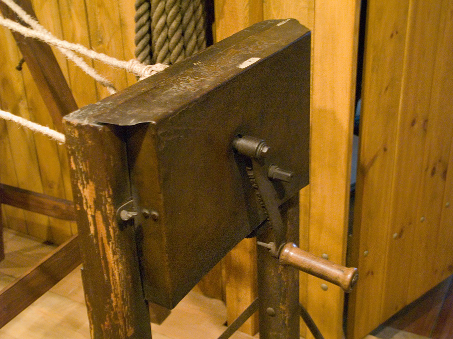 |
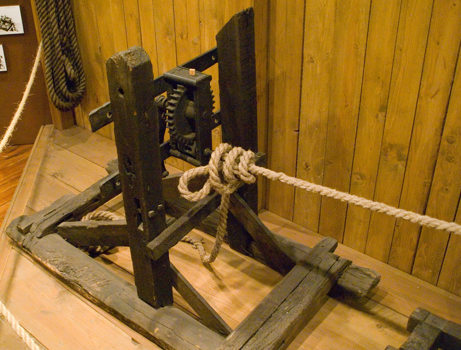
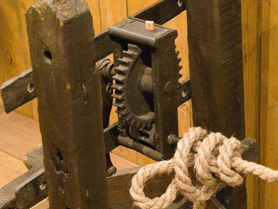
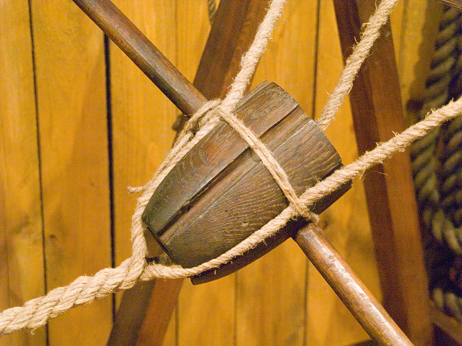
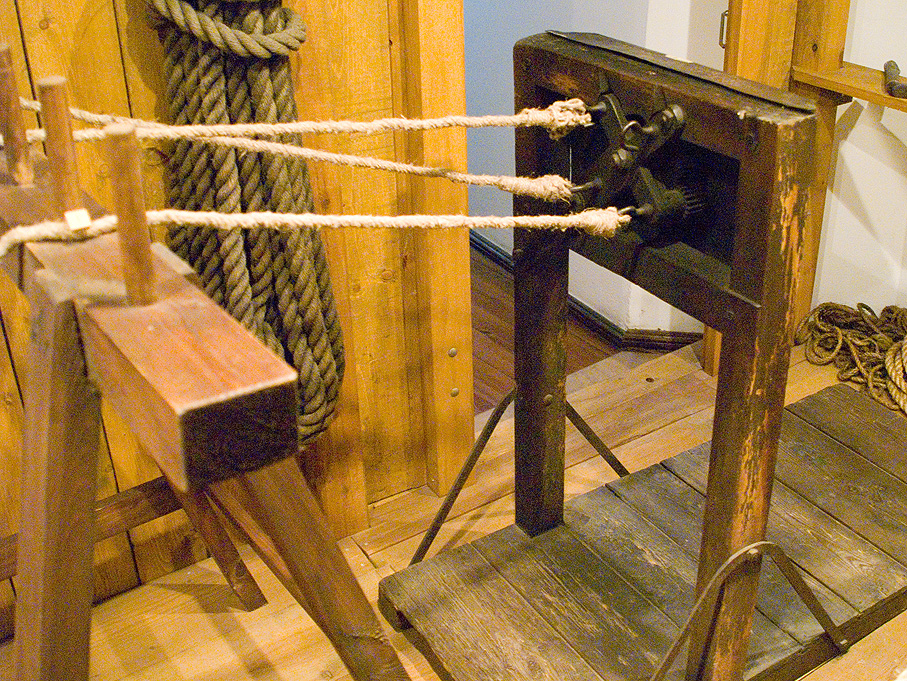
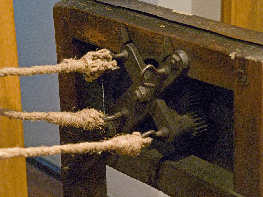
| Late
19th/early 20th century ropewalk in the Polish
Maritime
Museum in the Krantor/Dantzig |
|||||
Essentially, a ropewalk consists of a headstock with a planetary drive the gives the individual strands a twist against the 'lay' of the rope, while at the other end there is a tailstock drive that twist the rope together. A travelling bobbin (the denomination varies) ensures that the strands are separated and then fed together in a controlled fashion. However, Bernard Frölich (1999) suggested that, when one keeps the strands apart at the tailstock end and then twists them together, the rope will start forming from the middle of the walk, progressing towards the headstock and tailstock. It is this principle that was used for the miniature ropewalk.
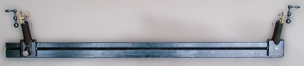 |
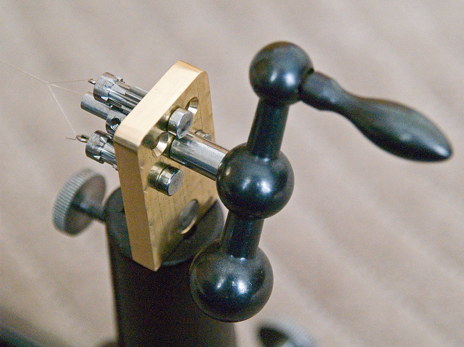
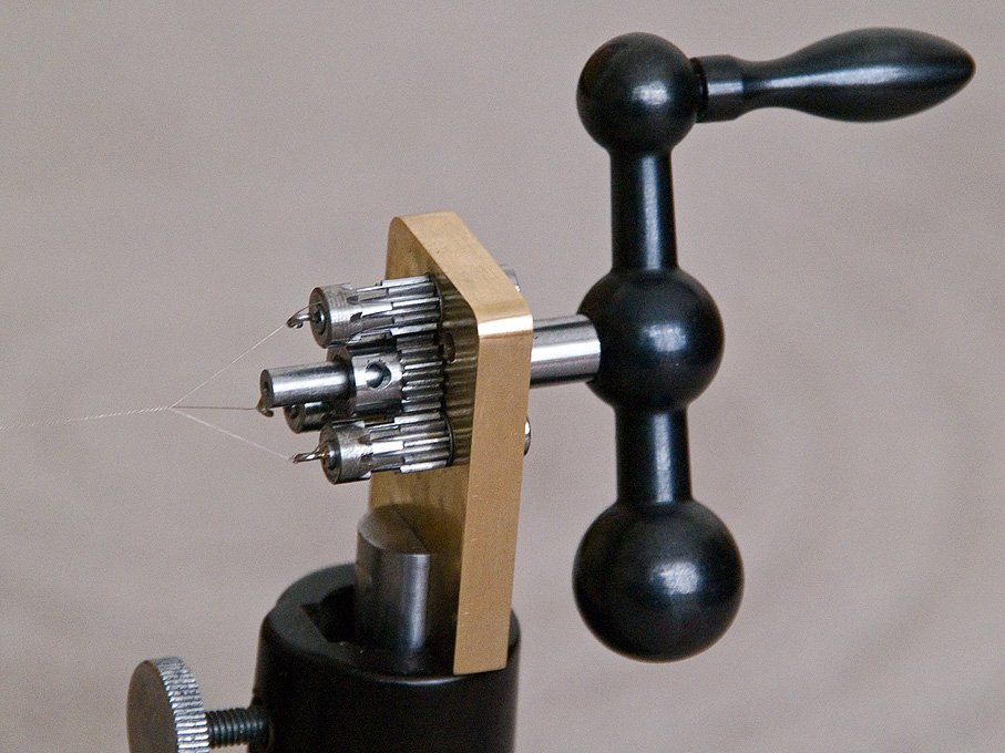
Apart from the gears that were mostly bought for the purpose, the ropewalk was constructed from pieces found in my scrap-box. The design evolved while I was assembling it, so some aspects are not as well thought-out as I would wish. For instance, for the headstock I should have purchased six pinions and installed them permanently in a hexagon. I was too mean and bought only four.
 |
 |
 |
 |
 |
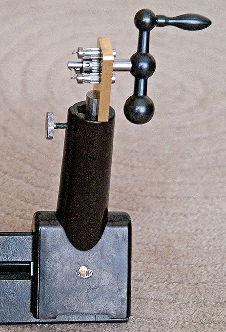 |
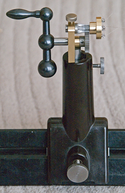
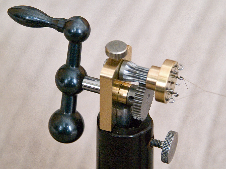
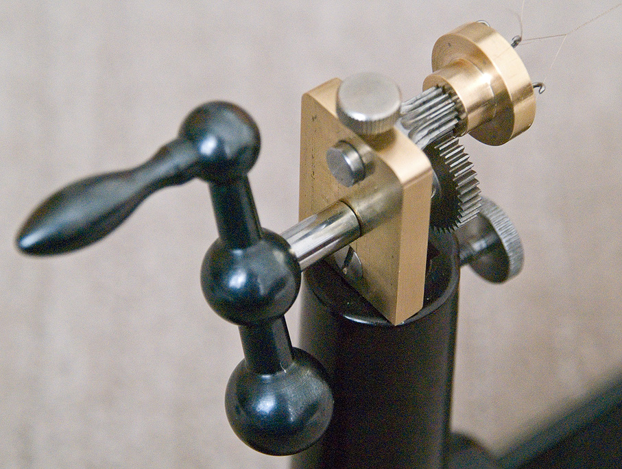
The body of head- and tailstock is a small slab of 6 mm brass. The holes for the shafts were drilled and reamed to size. On the side that would have to take up the pull of the rope a 90° cone was sunk to create effectively half a cone bearing. This a better defined position than just a cylindrical bearing. The driving shaft in the headstock was left somewhat protruding to allow fixing at a later date a clamp for holding very thin wires for twisting them together. The hooks were bent from iron wire and hard-soldered into the shafts, as were the hooks in the driving plate of the tailstock. The driving shaft of the tailstock can be blocked by a thumbscrew that acts on a small brass pad, but the very thin ropes that I am making do not exert that much torque, so this may have been not necessary.
The steadies of an optical bench are not meant to travel, they are just set by a thumb-screw that screws into a triangular groove of the bed. However, the tailstock of a ropewalk has to move to allow for the shortening of the strands and the rope while being twisted together. I added round gibs made from aluminium rod. Round because I was to lazy to reproduce the odd triangular shape of the grooves. The tailstock is eased by hand to allow for the shortening because the rather long stems of the steadies lead to canting and thence to breaking of the very delicate ropes.
Depending on the direction of cranking, left- and right-handed rope with three or four strands can be made.
Reference
FRÖLICH, B. (1999): L'Art du modélisme.- 304 p., Nice (Editions Ancre).