Building a filing-machine has been on my agenda
for quite some time. With this in mind, I was able to purchase a
treasure lot of rare
Vallorbe
machine-files. The lot contained round, half-round, tri-angular,
and square files starting from 1 mm diamater resp. 1 mm x 1 mm
cross-section, going up to 4 mm x 4 mm, and of various cuts.
Unlike most other types of files, machines files are prismatic
across their whole length and have uncut shanks at both ends.
I first thought about converting my only moderately useful
Proxxon
DS 230/E scroll-saw into a filing machine. However, the
table would not tilt and the holders for the saw blade were
difficult to adapt. Then a broken jigsaw attachment for a
power-drill came into my possession. Having no need for such
attachment, the idea of converting it into a filing-machine
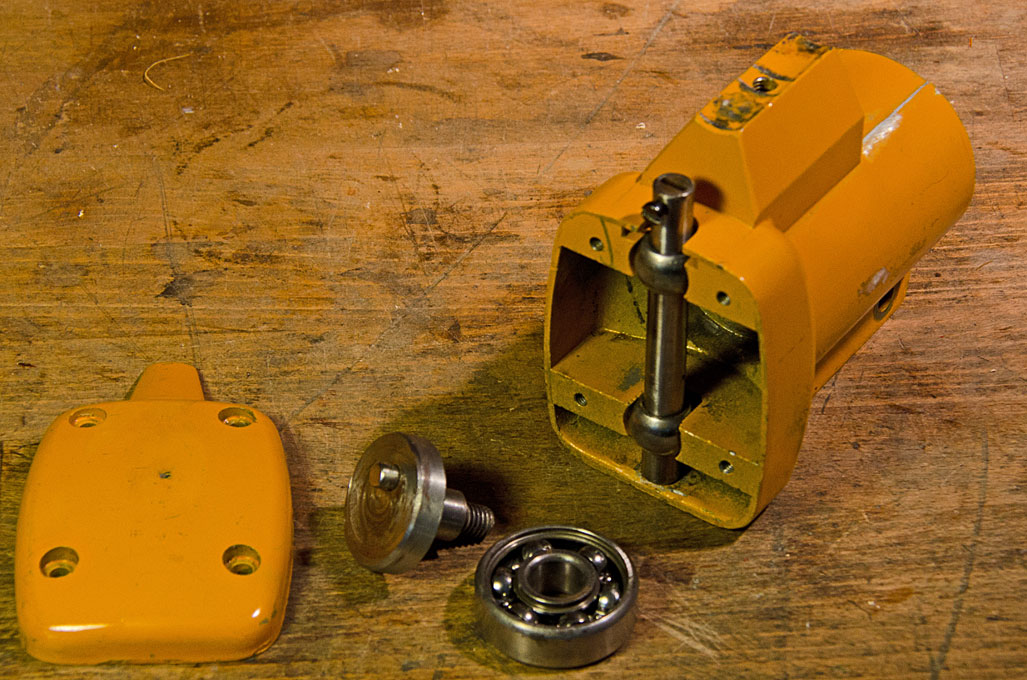
emerged. The jigsaw was completely stuck nothing moved, and the
sole plate was broken off. After having drilled out the screws
that held the lid, the reason was obvious: it was completely
filled with saw-dust, including the ball-bearing, presumably
because it was upside down used under a saw-table. After
dismantling and thorough cleaning it worked again. This meant,
that I had the mechanism and the casting forming the basis for a
filing-machine. According to the tables in the machine catalogue
fo 1913, from which above illustrations were taken, the maximum
stroke frequency would be around 400 per minute for hard
materials, or less for softer materials. I sourced in China a
geared electric DC motor that is rated to have 400 RPM at 12V. The
output torque should be sufficient for the machine to be driven
directly.
 |
 |
 |
 |
 |
 |
 |
 |
 |
 |
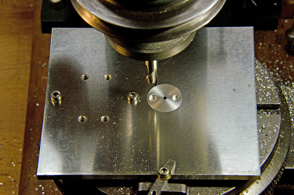
Set-up for
milling the
tilting table bearing |
Praparing the jigsaw
casting for conversion
|
Milling the bearing barrel
halves
|
Tapping the
mounting holes
|
Squaring
the table edges
|
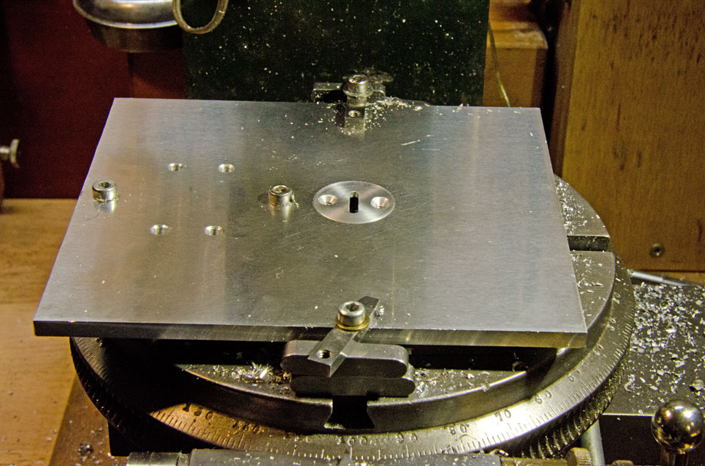
Bearing barrel mounted to
underside of table
|
Milling the slot for the
holding-down bolt |
In order to minimise the slot for the files, allowing to work on
small pieces, the rotational axis for the tilting machine table
should be in its surface plane and it also should not move out of
the centre line. The foot of the jigsaw was arranged in a similar
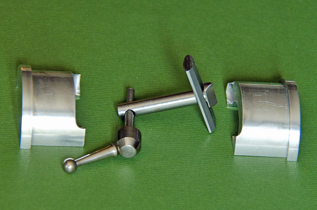
way and only needed to be adapted. The table will rest on a
half-round barrel that can be clamped down onto a corresponding
bearing surface. I had some 40 mm diameter alumium in my stock,
from which I turned the barrel. It was sawn into half to be
screwed to the aluminium machine table. The bearing for the barrel
was milled out accordingly. Similarly, some of the future bearing
surfaces on the casting were milled flat, which just went up to
the capacity of my milling machines. Luckily the zinc die-cast
material of the jigsaw housing is easy to mill.
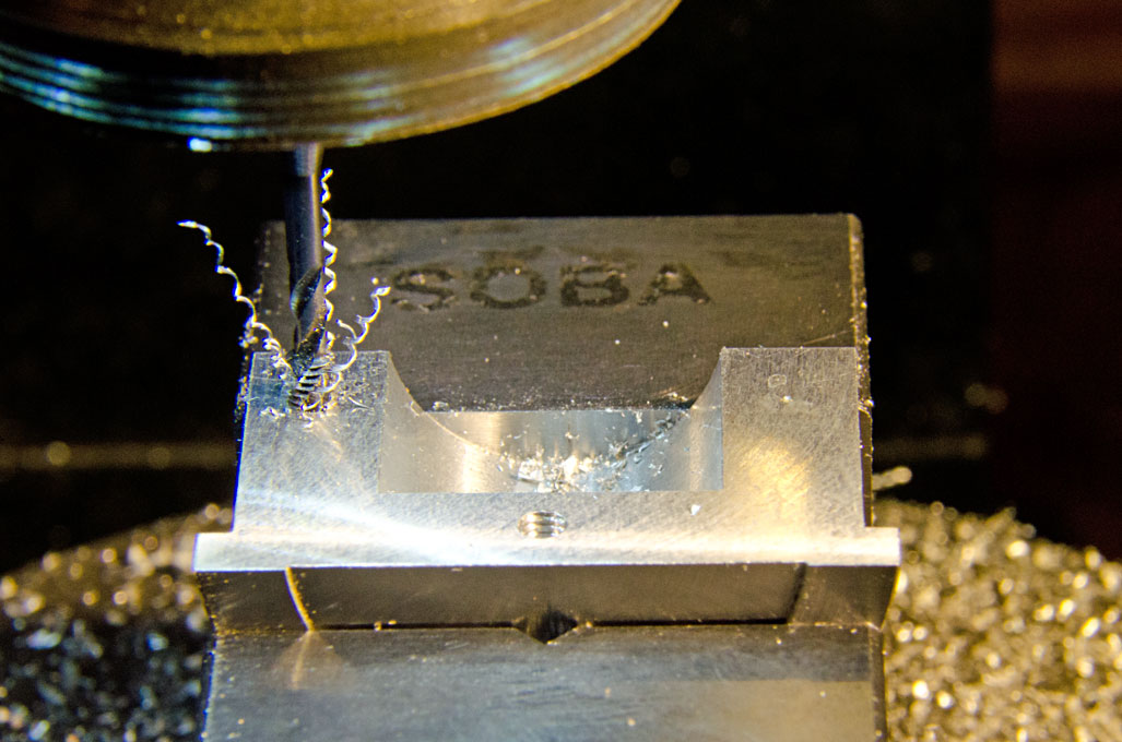
The two halfs of the bearing barrel were clamped end on in the
vice after careful alignment. With a fly-cutter the surface was
milled perfectly flat and the diameter reduced to bring the
rotational axis of the table into its surface. The position for
the barrel was marked out on the piece of 4 mm aluminium that will
become the table. In the following step the positions for the
mounting screws were marked out and drilled mit a 3 mm drill on
the drill press. The two half-barrels then were stuck onto the
table with a few drops of cyanoacrylate glue after careful
alignment. The positions for the mounting screws then were marked
with a transfer-punch. A light knock separated the parts again,
which were transfered to the mill for drilling and tapping M3 of
the mounting holes. I usually start the tap on the mill with a few
turns to ensure it is perfectly concentric to the hole and
vertical. The tapping was completed by hand.
Sqaring the edges of the aluminium plate for the table proved to
be just at the edge of the capacity of the milling machine. The
plate was clamped to the vice on the mill with a C-clamp and the
edges milled flat. With the bearing-barrel screwed onto the
underside of the table, the assembly was bolted to the table of
the milling machine for milling the slot for the holding-down
bolt. This holding down-bolt is locked using an excentric lever.
The excentric rod was turned from a piece of steel, while the
actual lever with the ball end is a recovered piece from a similar
broken commercial product. For other pieces of equipment I turned
such levers myself using the
ball-turning
attachment.
The next part to be tackled was the socket for the overam holder.
An overam is needed for guiding the delicate machine files and for
taking up the side pressure when filing. The foot for the sawing
table on the casting was hollow and sort of house-shaped inside. A
piece of aluminium bar was carefully milled to shape and size to
provide a snug fit. Two tapped holes will locate it in place.
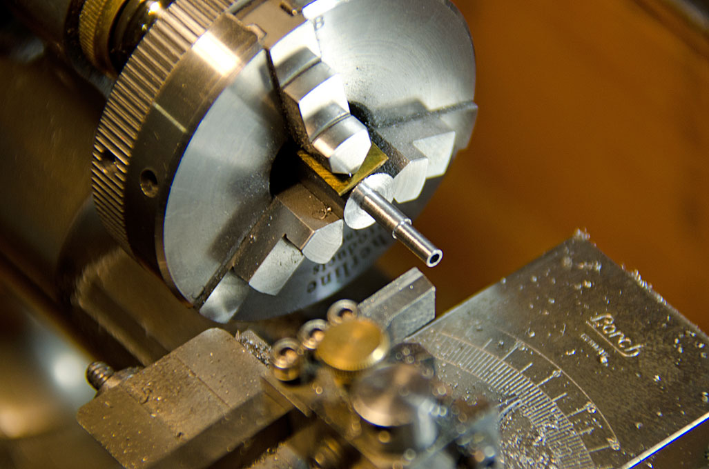
Drilling the 10 mm hole for upright round bar proved to be taxing
for the capacity of my machines. There was not enough clearance
under the mill for such large-size drill. Due to the hole being in
one end of the part, it would also not fit into the four-jaw chuck
for boring out. In the end, I realised a long-planned project and
made an adjustable boring bar from a piece of 8 mm rod. For this I
also had to fashion a collet with three set-screws for 8 mm bars
etc. With this boring bar it was easy to drill out the hole with
an excellent surface finish.
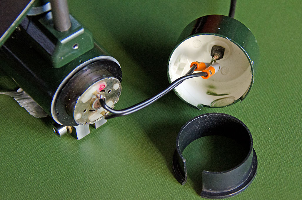
As can be seen on the photograph showing the disassembled jigsaw,
the piston for the saw-blade was guided by two self-aligning
bearings. These bearings essentially are two cast-iron spheres set
into slots and that were bored for the steel piston of 9.5 mm
(3/8") diameter. Lubrication relied on the self-lubrication of the
graphite in the cast iron and the system had already considerable
play in consequence. Therefore, the spheres were bored out to
accept 10 mm self-lubricating bushings for 8 mm rods. These came
from China through a well-known Internet service and are
presumably normally used in computer printers and the like.
Self-lubriacting bushings were chosen, because oiling would have
been difficult under operating conditions. The new piston was
fashioned from 8 mm polished and calibrated silver steel.
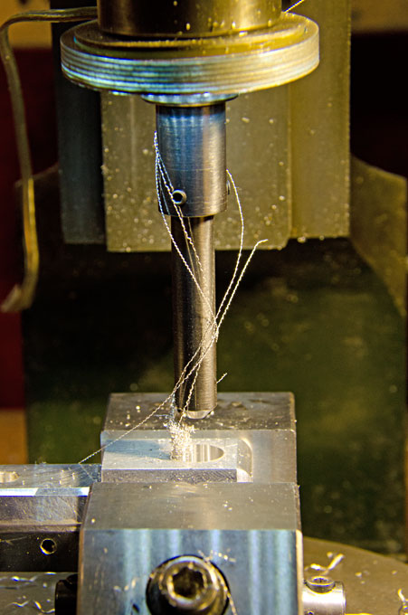
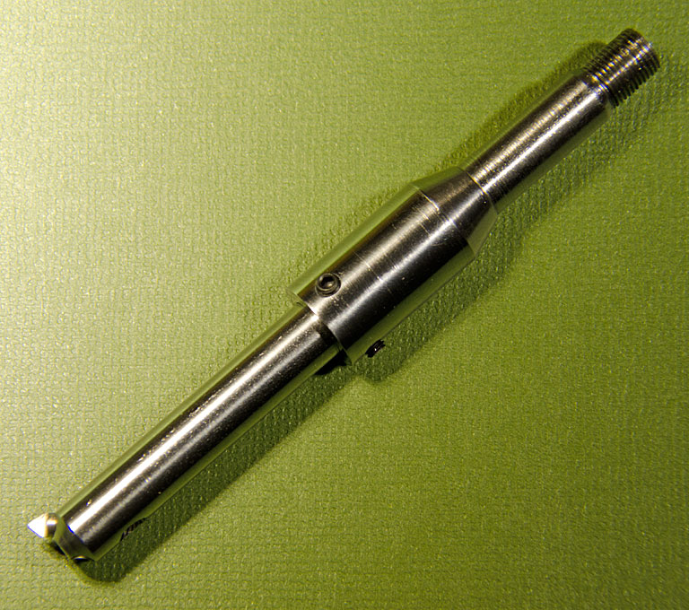
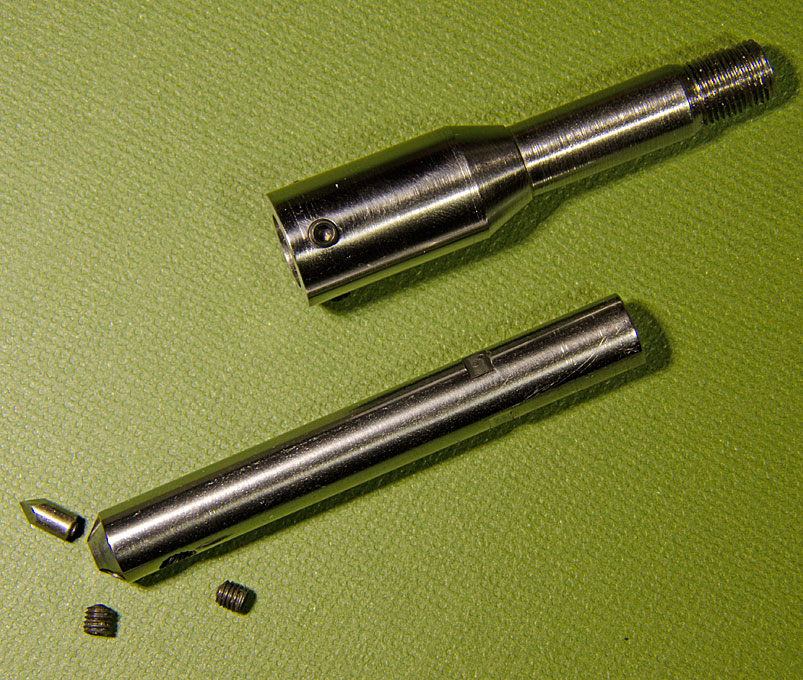
The original drive-shaft was made from a steel of rather poor
machineability. It was impossible to achieve a satisfactory
surface finish on it with the watchmaker's lathe. As I intended to
change the original design slightly anyway, a new drive-shaft was
turned from a piece of 32 mm round steel. This shaft was bored out
for the 6 mm diameter gear-box output shaft to which it will be
attached with a set-screw. The whole crank mechanism was also
replaced, as it was badly worn due to steel-on-steel sliding
friction without any lubrication. Originally a round pin was
sliding in the cross-head slot. The new design provides for more
positive guidance. A proper cross-head bearing block was machined
from brass (bronce would have been better, but I didn't have any
in my stock) and will slide in a new cross-head. The new crank was
bored for the cross-head pin at different distances from the axis,
which allows to set the stroke of the machine at 10 mm, 15 mm, and
20 mm. However, it will be necessary to almost dismantle the whole
driving mechanism to change the stroke, as the set-screws for the
cross-head pin would not be very accessible. The maximum stroke of
20 mm may not be possible with the current file-holder design due
to sufficient clearance under the table, when it is inclined.
Practical experience will show, whether a 15 mm stroke is
satisfactory.
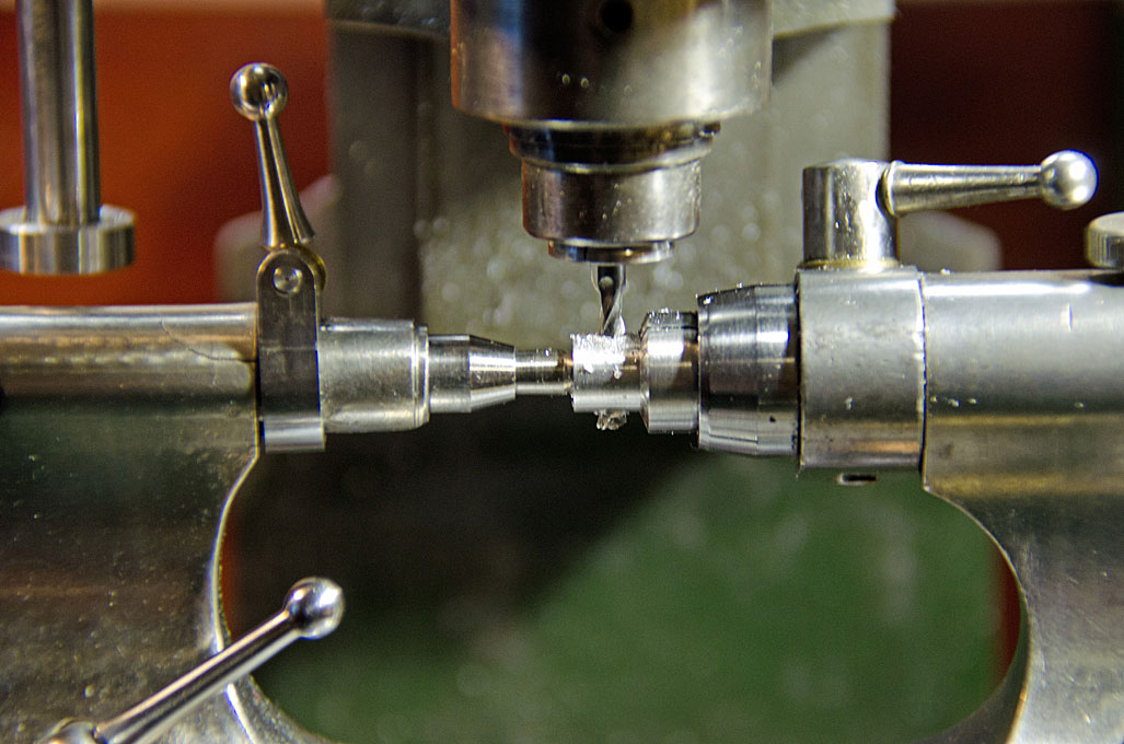
The machine-files come in various shapes and sizes, therefore,
various holders to hold them securly and parallel to the axis of
movement had to be designed. I opted for sockets into which
bushings for the various file sizes will fit. Additional bushing
were made to hold fine jewelers saws, so that the machine can also
be used as fret-saw. The holders to attach onto the driving piston
and the guiding piston in the overam were turned from steel. The
holders were tapped M3 for two set-screws on opposite sides that
will act directly on the files. The bushings were turned from
aluminium with a selection of internal diameters to fit the
available files. They were then cross-drilled to allow the
set-screws in the holders to pass through. In fact, the holder on
the driving piston has two sets of set-screws set 90° apart in
order to allow the orientation of triangular and rectangular files
as needed. The guiding piston had a 8 mm x 1 mm thread cut on the
watchmakers lathe, as I had a suitable tap for this M8 (fine)
thread. Two thumb-nuts with this thread were machined from
aluminium (to keep the mass of the guiding piston low). They give
a spring around the piston the necessary intial tension. It is
necessary to keep the very thin (1 mm diameter) files under
tension in order to prevent them from buckling during the
up-stroke.
The next item to be tackled was the overarm. There are three
ways in principle to guide the files or saws: 1) the file/saw
is tensioned in a frame and this frame is moved up and down as
can be seen in most antique machines pictured above; the
advantage of a precise movement and a constant tension of the
file/saw comes at the expense of a bigger moving mass so that
the machine has to fixed securely to a table; if the frame is
not designed in a way that it can be removed, the use of stub
files and work in internal cut-outs is rather inconvenient, 2)
the frame is fixed and a guiding piston moves in a sliding
bearing in an over-arm; the file/saw is tensioned by a
coil-spring which implies that the tension changes over the
movement; the advantages are that the over-arm can be easily
swung out of the way, when stub files etc. are to be used, or
the file/saw has to be threaded into a cut-out; also the
moving masses are smaller, 3) the over-arm is actually a
leaf-spring, as is the case for many older fret-saws; this
design is unsuitable for a filing machine, as the movement is
not precisely linear, but has a slight swing, which is
actually desirable in a fret-saw. The old jig-saw used only
allowed a design according to point (2).
The overarm was fashioned
from a square piece of aluminium. The holes for the
self-lubricating piston-bearing and the upright were drilled
and bored out to exact dimensions. In order to give it the
appearance of a cast part, a relief was milled into the sides
of the arm. The ends were rounded on a filing disc mounted on
an arbor in the lathe (such filing discs seem to extremely
rare today, but I was able to acquire one some years ago). The arm was then slotted for the tensioning bolt.
This bolt was found in the scrap-box of old watchmakers lathe
parts, but had the unusual thread of 7/32” x 24 tpi. Luckily,
I had acquired some years ago a lot of odd taps that contained
a matching one.
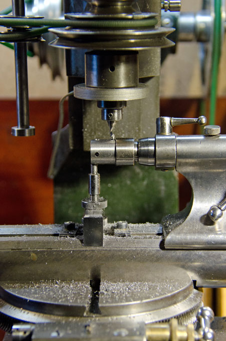
As the filing-machine is designed to work on very small
parts, a near-zero clearance around the files is needed. Given
the different sizes of files available, the solution is
changeable table inserts for the table. The blanks for these
inserts were cut as squares from 2 mm sheet-aluminium. A 2
mm-hole was drilled through the middle of the squares, which
then were mounted as a package on a suitable lathe arbor to be
turned round. The same arbor was transfered to a square
collet-holder. The collet-holder in turn was held in a vice on
the horizontal milling machine. This set-up allow to drill and
countersink the two mounting holes symmetrically for two M2
screws.
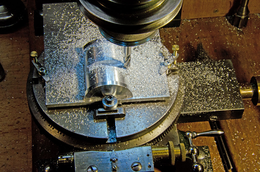
The final piece of machining is finishing off the table blank
produced earlier. A recess for the inserts had to be made.
Normally, this would be a job for the lathe faceplate, but even
with the rising blocks the centre height of my WW Lorch-lathe
would have not been sufficient. Therefore, I screwed the table
blank with spacers onto rotary table of the milling machine, which
had been carefully centered before. The marked-out blank was in
turn centered on the table. This set-up allowed to round-mill the
recess to a depth, where the inserts are flush with the surface of
the table. In the same set-up the clerance slot for the files was
milled out to allow the inclination of the table to 45° in both
directions. Using an insert as template, the mounting holes for
them were drilled in the same set-up. This allowed to screw-down
the inserts in their place and to mill the clearance-slots in them
in situ, thus avoiding alignment errors. Again, in the same
set-up the holes for the table-bearing barrel were countersunk,
which had not been done before, because the table surface was kept
protected by its plastic film.
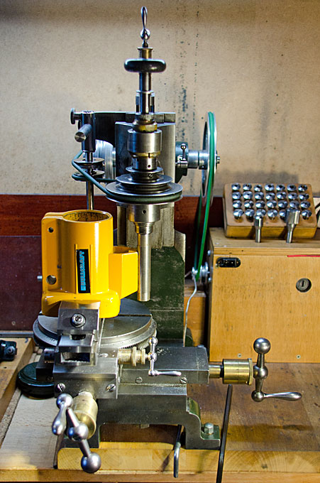
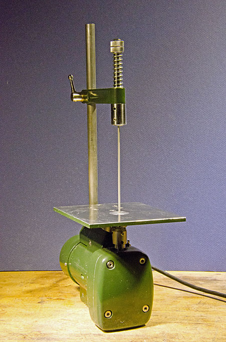
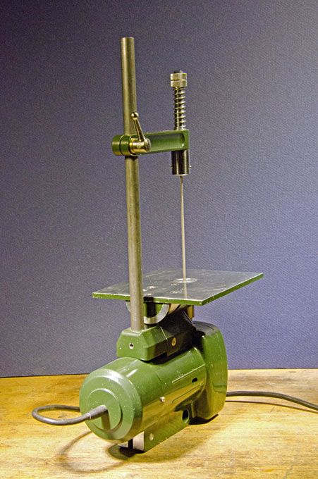
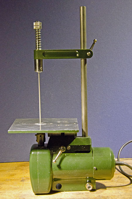
With all the machining completed, the various castings were
cleaned up for their cosmetic appearance and lightly sanded to
provide a better key for the new paint. The areas not be painted
were masked with tape and and any openings stuffed with toilet
paper. The castings were given a light coat with a filling primer,
while the fabricated parts were just given a coat in an ordinary
primer. After some light sanding and thorough de-dusting the parts
were spray-painted in my favourite colour for machines, in RAL
6007 'Bottle Green'. I find the combination of bright steel,
polished brass details, and the dark green aesthetically very
pleasing.
On the images above there are two parts visible that have not been
discussed yet: a round cap that will close-off the electrical
installations of the motor and a clamp to fix the machine at the
workbench. The round cap actually is a bakelite cover for some
electrical home installations and which had almost the right
internal diameter. I just needed to enlarge it on the lathe by a
few tenth of milimetres. It is held by two M1.6 cheese-head screws
for which the casting was drilled and tapped. The clamp belonged
to an obsolote electrical drill. The reciprocal movement of the
filing machine will necessitate some form of fixation, or it is
likely to jump around a bit. In addition, the high centre of
gravity of the machine would make working with it like this rather
unstable.
It was now time to assemble the various parts. The ballbearing was
thoroughly greased and pushed back into its seat. Next the drive
shaft was pushed in and the crank and piston assembled. Holding
the motor concentric in the casting initially caused a bit of
headscratching, but then I chanced in the scrap-box upon a set of
plastic reduction rings from a machine (they may have well
belonged to the very jig-saw) and one of them had just the right
internal diameter to fit the electric motor. The drive-shaft was
secured with a set-screw to the gearbox output shaft. The
scrap-box furnished also a rubberised cable complete with kink
protector, for which the bakelite cap had been drilled out. When
the assembly was complete, the machine was ready for a first
test-run.
During the test-run I noticed something previously overlooked: the
piston did not have a firm guide to prevent it from rotating. It
was thought that the crank would give enough guidance, but it
still wiggled somewhat during each stroke, which is rather
undesirable for precision work. Therefore, a brass guiding plate
was added to the cross-head that slides along the crank-plate of
the drive shaft and thus prevents the piston from rotating. One
could have also made a new crosshead that touches the crank-plate,
but I wanted to avoid a steel on steel contact and the guiding
plate can be adjusted for wear.
With this the machine is essentially complete and ready to run.
Here are three short videos that show the machine on a dry-run:
video-1,
video-2,
video-3. It still needs to be
tested in anger ...
 |
 |
 |
 |
 |
 |
 |
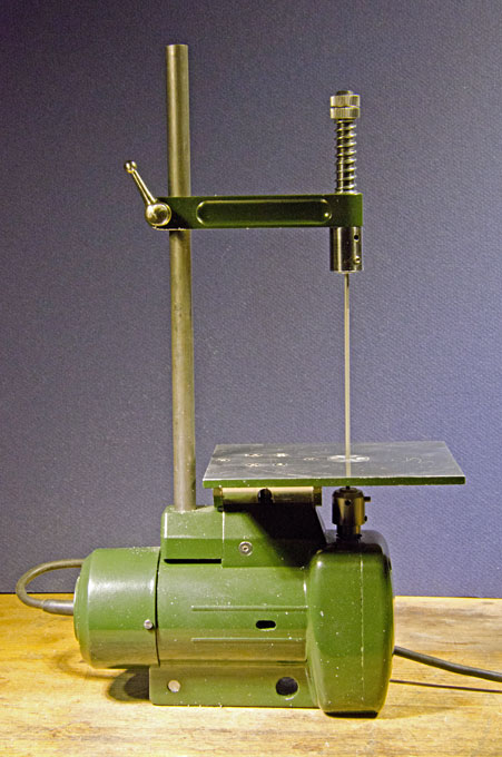
The completed die-filer
|
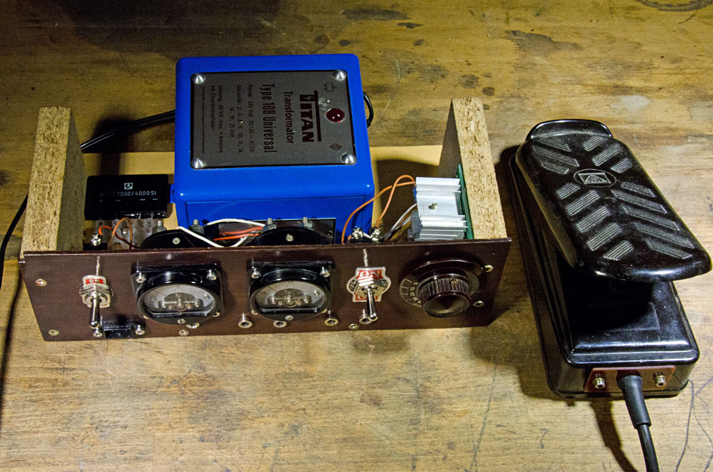
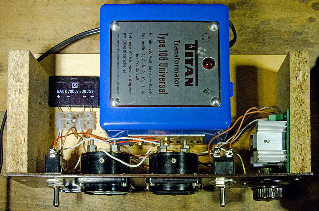
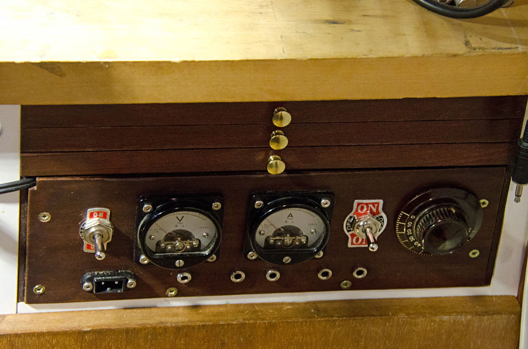
Reversible and variable
powersupply for 9V and 15 V
|
Testing the diefiler in anger requires a suitable power supply
with enough ampères and the right voltage. After my large Proxxon
transformer blew out I constructed from mainly scavanged parts a
unit that would fit into the worktable. From the estate of my late
father I had a large transformer, a rectifier, and a nice
'antique' volt- and ampère-meter each plus various kinds of
sockets and a radio knob. I bought an electronic speed-controller
and two switches from Chinese sources. One switch allows to change
between the two voltage ranges and the other is set up as a
reversing switch. Depending on the size of leads I am either using
small Japanese-type power-supply plugs or 3.5 mm mono-plugs and
sockets for both are provided. In addition, I provided sockets for
4 mm laboratory plugs, one going through the speed-controller, the
other directly to the rectifier.