last revised 15/07/09
A Geared Dividing Head
Making equal
divisions on the circumference or on the face of a turned part is
a frequent shop task. Think of drilling holes for the spokes of
wheels, cutting a spur gear, milling flat-sided columns,
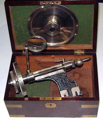
cross-drilling etc. The watchmakers lathe usually has some simple
diving capability built in as the pulley has 60 equally spaced
holes drilled in one of the faces. Some lathes sport even two or
three rows of holes. A spring-loaded stop is provided. This
indentation capability, however, is meant to be used with the
double filing rest. The milling and grinding attachment can also
be used. If you have one on a vertical slide, almost every type
of gear etc. can be cut that has the divisions of
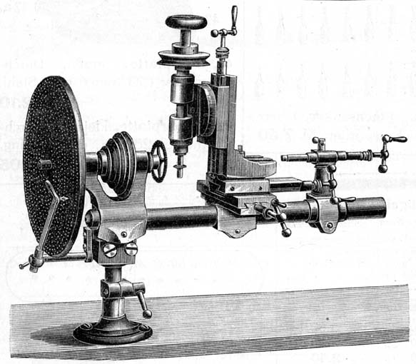
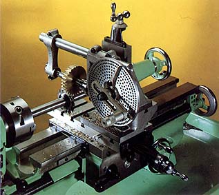
2,4,6,10,12,15,20,30, and 60. A rotating headstock, as was available from some manufacturers,
makes the arrangement more versatile (Figure 1). The ultimate would be a large dividing
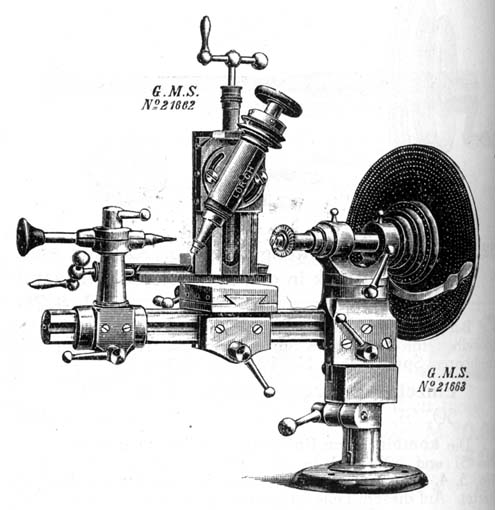
plate mounted either on the back of the headstock, or on the back
of the milling spindle (Figure 2). These dividing plates fetch premium
prices these days on the second-hand market.
I have been tossing
about with the idea to make a miniature universal, geared divind
head for some time. This was meant to take 6 mm collets and other
work-holding devices, such as the 3- and 4-jaw chucks. This would
be for use on the milling machines and could be used for exotic
tasks like cutting microscopic bevel gears. Then I happened to
acquire, together with some other lathe stuff, a not
so-good-anymore 6 mm grinding attachment (LS&Co. No. 31a).
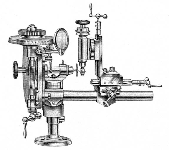
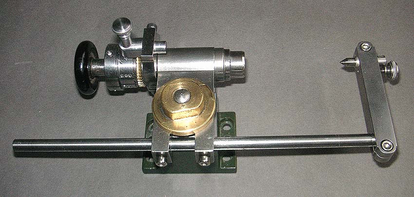
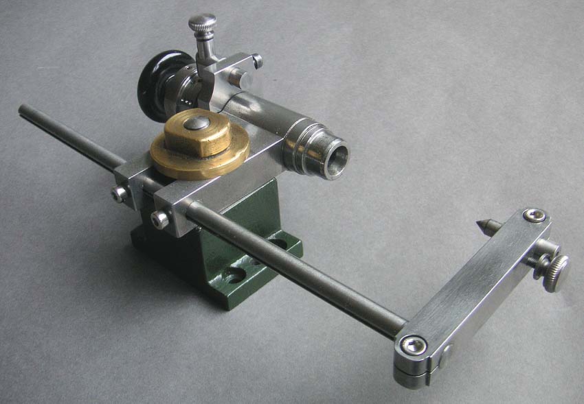
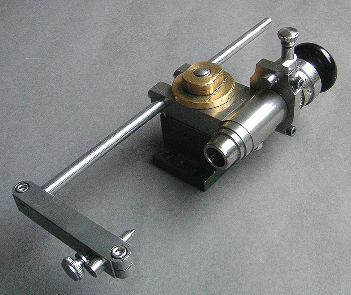
Inspired by some exotic Lorch equipment (Figures 3 to 5), I designed a geared dividing attachment
that fits onto the grinding attachment.
|
|
|
|
|
|
|
|
|
(1)
Wolf, Jahn & Co. D-bed lathe set up for wheel-cutting (from my
original copy of a 1912 WJ&Co. catalogue).
|
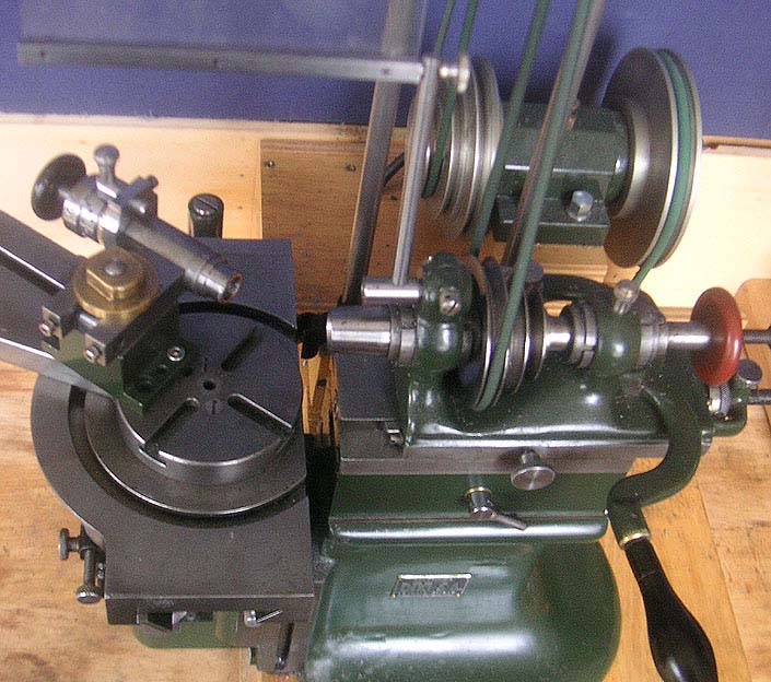
(2)
Lorch, Schmidt & Co. D-bed lathe with rotating headstock set up for
wheel-cutting (from my copy of the famous 1911 catalogue of the supply
house Georg Jacob G.m.b.H., Leipzig).
|
(3)
Picture of worm-driven diving apparatus on D-bed lathe (from an undated
Lorch, Schmidt & Co. catalogue
|
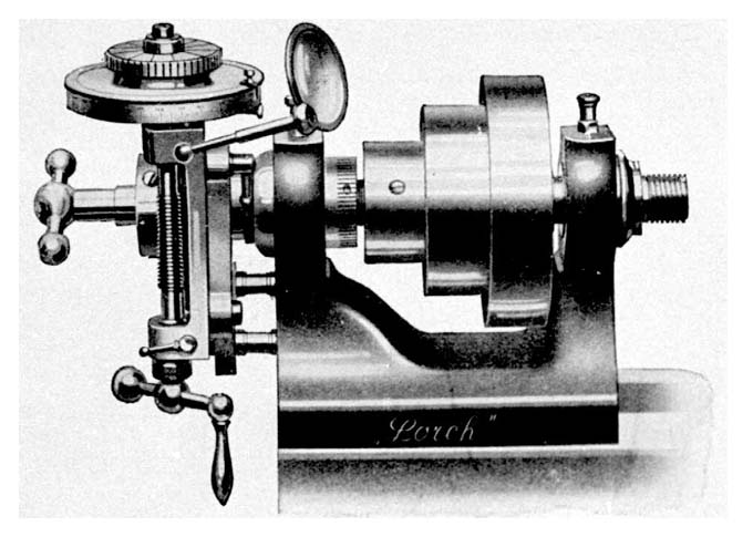
(4)
The same type of dividing apparatus fitted to a Lorch LL lathe
headstock (from the equally sought after 1937 catalogue of the supply
house Flume GmbH,
Essen/Berlin)
|
(5)
An original for a LL(?) lathe recently seen in an Internet auction
catalogue (apologies if I have violated any copy rights !)
|
(6)
Myford
dividing head from
a recent catalogue
|
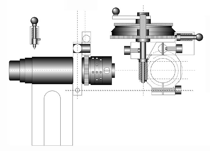
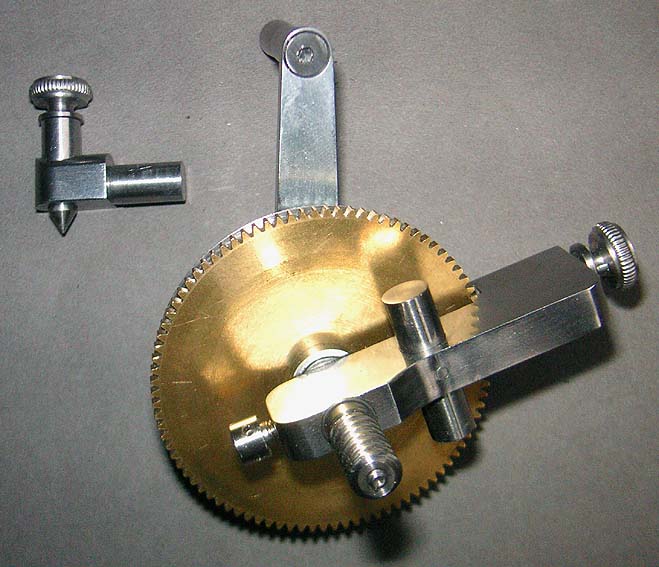
(7)
Working drawing for the dividing attachment.
|
The intention was to alter the
historic substance of the grinding attachment as little as
possible. However, a previous owner had already used it for a
similar purpose and drilled a hole for a spring-loaded stop. So
in the end I became less concerned.
The divind head was to be used for
direct dividing, using a drum with three rows of holes (6,8,10)
allowing the most common simple divisions of 2,4,(5),6,8, and 10.
A 40 teeth worm-wheel and worm together with a plate of 90
indentations would allow 3600 division steps, i.e in increments
of 1/10 of a degree. In addition, the self-locking properties of
of the worm would allow to carry out various circular milling
operations. The indirect dividing attachment can be exchanged for
the direct dividing stop by simply loosing one screw.
For the conversion I replaced the
two-step pulley with the dividing drum and the worm-wheel coupled
together with two pins. The original collar to tighten the pulley
down on the spindle was retained, but the slot-head screws were
replaced by M2.5 Allan screws, for which the head was turned
down. A clamping bracket fits on the cylindrical part of the
grinding attachment's body (Figure 18). In this way it can be turned around for
fitting the attachment either parallel or perpendicular to the
lathe axis. A stub arbor is used to mount the two types of
indexing gear.
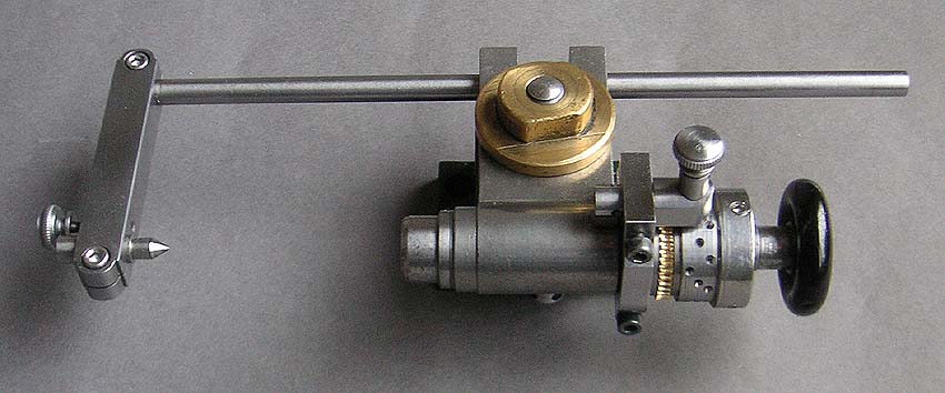
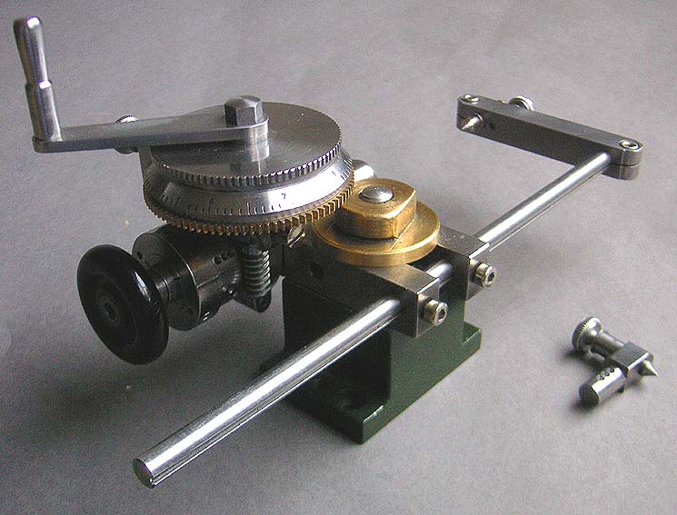
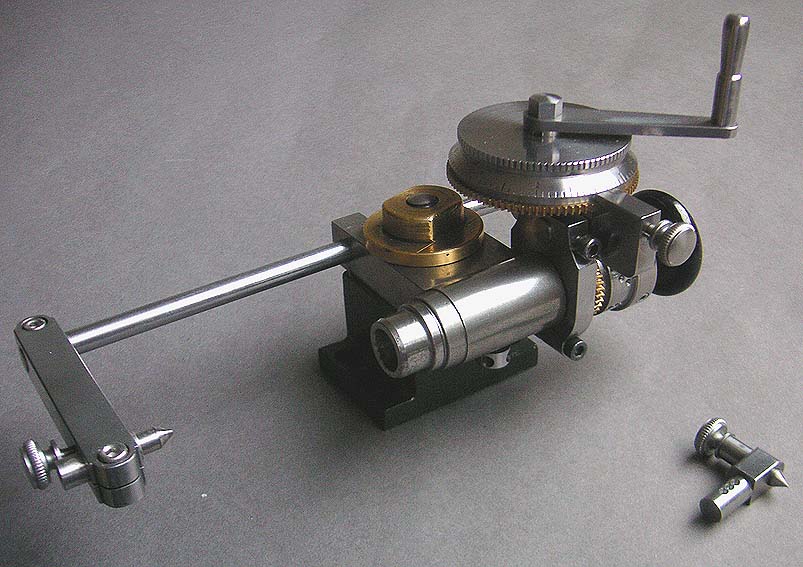
The indirect dividing gear (Figure 12 to 17)
consists
of a steel body that provides a simple cylindrical bearing for
the spindle that carries the worm on one end and the divind drum
at the other. The indexing wheel is a commercial brass 90 teeth
spur gear. The zero-adjustable drum (with friction locking) was
graduated on the milling machine using the spur gear as template.
Numbers were stamped in with the help of a little gadget that
kept the punches perpendicular to the bevel. The knurl was cut
with a milling cutter. The locking pin is spring loaded as can be
seen in the drawing (Figure 7). A crank allows easy turning for circular
milling etc. By loosening one screw, the worm can be disengaged.
The dividing head fits onto the 6
mm D-bed lathe cross-slide directly. Since in the WW-lathe the
centre-height above the cross-slide is higher by 1 mm, a spacer
had to be made. On the Dixi mill it can be either mounted
directly or on a raising block to provide clearance for the
larger chucks (Figure 8 to 11).
|
|
|
|
|
|
|
|
(8) Mounted on a
rasing block for use on the milling machines (this gives clearance for
3- or 4-jaw chucks)
|
(9) dito.
|
(10) dito.
|
(11) dito.
|
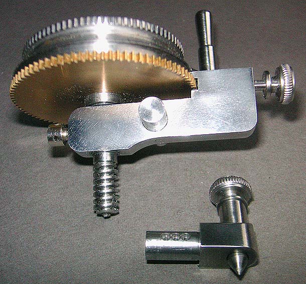
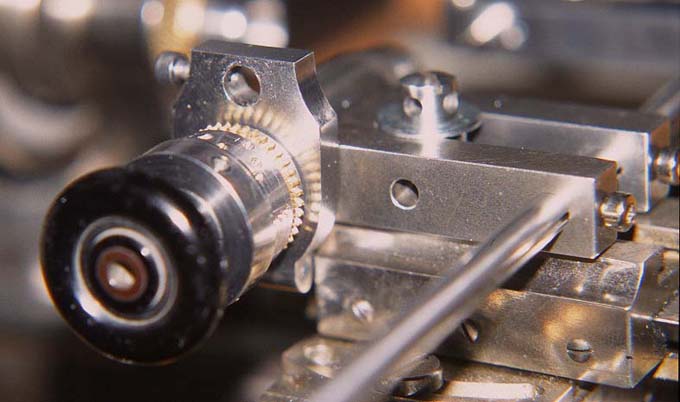
(12) Fitted with
worm drive and dividing plate for indirect dividing
|
(13)
Fitted with worm drive and dividing plate
for indirect dividing
|
|
|
|
|
|
|
|
|
|
(14) dito.
|
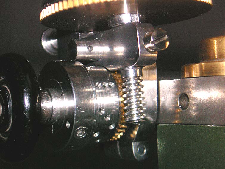
(15) Worm drive
|
(16)
Worm drive and indexing pin
|
(17) Worm drive
and indexing pin
|
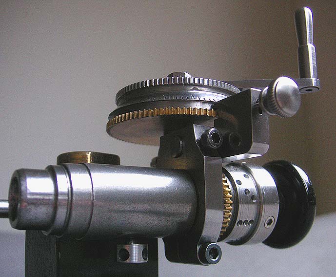
(18) Mounted on
the lathe cross-slide, showing holder for index pin or worm drive
|
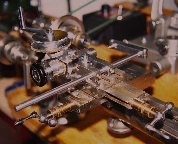
(19) Complete
indexing attachment mounted on lathe cross-slide
|
(20) Indexing
attachement mounted on Dixi miller
|
In shipmodel building
from time to time slender and tapered pieces (e.g. masts or
yards) have to given facets or need to be cross-drilled. For this
purpose a support at the outward end is necessary. Inspired by
the diving head that fits onto Myford vertical slides (Figure 6), I also designed a
tailstock support (Figures 8ff.). A 6 mm hole was drilled and reamed for a
sliding bar to be clamped in place. The 'tailstock' has a short
cylindrical runner that can be tightened by a screw and accepts
the the standard LS&Co. or WJ&Co. centres. In this way I
have the whole collection of hardened male, female, half etc.
centres available.
Contact:
webmaster at wefalck dot eu