last revised 31/05/11
Restoring the Wolf,
Jahn & Co. Model 'A' Milling Machine
This restoration had a number of surprises in store. The main
spindle has a thrust ball-bearing, but during an earlier
restoration a few of the balls seem to have disappeared. The
size of the balls is a rather awkward 3.155 mm rather than a
more logical 3.175 mm or 1/16". I could not get such replacement
balls and fitted for the time being 1/16" ones - have to monitor
the bearing. Unfortunately one half of the bearing was machined
into the upper headstock bushing, so one cannot simply replace
the whole bearing. The designers some 100 years ago had a lot of
trust in the longevity of their material!
In fact, the machine
seems to have suffered some not so professional maintenance and
repairs. Whoever at some time took the x-spindle of the table apart seems to have had
no idea how the spindle anti-backlash arrangements work in a
watchmakers lathe-type cross-slide. Fitting it the wrong way
around he must have found the spindle to be too long and cut it
off !
Both table spindles
have a rather unusual thread of 7 mm diameter with a 1.4 mm
pitch. I had planned to replace them with
one of the discouraged, but standard M7x1 thread. This pitch
gives a rather slow feed, but it is easier to make feed
calculations then. However, I could not find a company (in
Vienna) that would machine for me such spindles at a reasonable
price. Prices quoted for the two spindles were in the same order
of what I paid for the whole machine ...
So in the end I
settled reluctantly
on commercial, threaded M6x1 bar. The spindles were made to
extend the full length of the slide. Previously, only a little
more than a quarter of the table could actually be reached
without rotating the table. This is probably sufficient for
watchmaking and die work, but not for my model engineering
purposes. The later BCA millers
have the casting of the x-slide extending the same distance left
and right of the rotating table, while the one on the WJ&Co.
is asymmetric. A pleasant surprise was
the split-nut on both cross-slide spindles that can be tightened
with two screws to make up for wear and to reduce backlash. They
were replaced with new ones fashioned from bronze and modelled
after old ones, but with the M6x1 thread, of course.
A common feature on
tightening nuts of similar cross-slides is the badly worn knurl.
Using a pair of pliers to tighten them seems to be very
tempting. Admittedly, I also use pliers, but I first put a
wooden clothes peg(!) over the knurl. As interim cosmetic
solution, the knurl on the original nuts was restored using the
geared dividing head fitted to the hand-shaper.
|
|
|
|
|
|
|
|
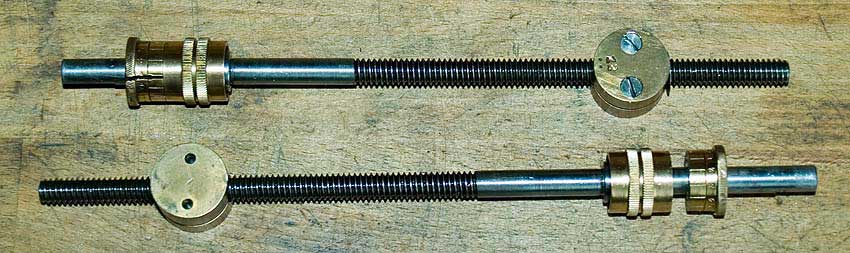
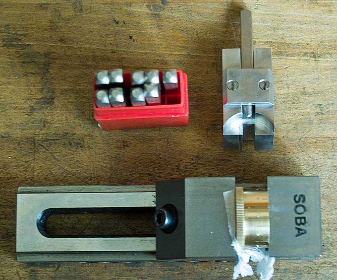
The
original
spindles and micrometer drums
|
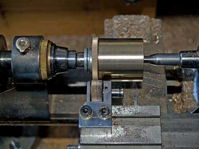
Knurling
the new
drums
|
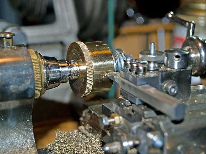
Engraving the
drums
|
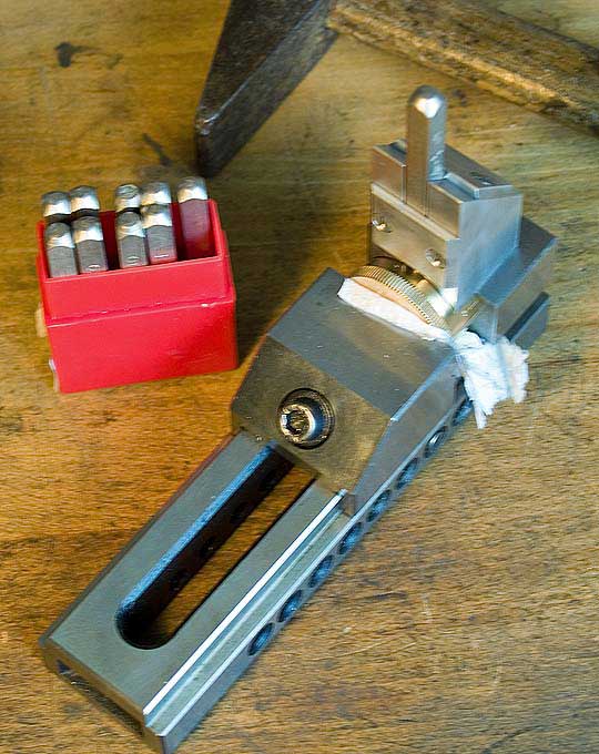
Stamping the numbers
using
punches in a jig
|
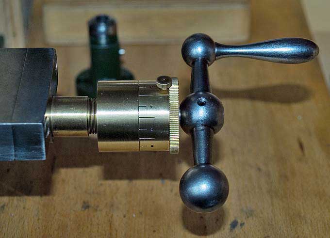
New micrometer
drum
|
Restored
cross-slide
|
When I eventually replaced spindles, the rather
worn and coarse original micrometer drums, which would not work
with the new spindle pitch anyway, were replaced with much
larger and better engraved ones. They were modelled after the
old ones, but became a positive lock for the zero point using a
small knurled screw. The knurling, engraving and stamping
processes in their manufacture are illustrated in the pictures
above.
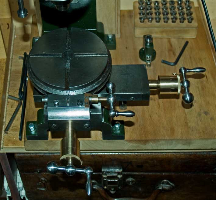
The table is not very ingeniously designed. It appears that it
is not actually meant to be turned under load, i.e. for milling
pieces round. All bearing surfaces are cylindrical, thus not
permitting very precise centering when the table is unlocked. In
addition the lock, a bolt with an excenter turned on, just pulls
down the central pivoting bolt. For this reason, the bolt does
not turn with the table, making the centering of the table a bit
awkward.
During an earlier
repair effort someone replaced the worm driving the
table with its arbor and crank etc.. The balanced ball-handle
crank was a rather crude imitation and the arbor was made
without understanding the cone bearing into which it would be
drawn with a nut, secured by a lock-nut. As this brass
replacement worm was already rather worn, I replaced it with a
newly made on in steel as the original one. A compassionate
owner of a similar miller kindly supplied me with pictures of
the dismantled worm, so that I was able to replicate the parts.
Originally hexagonal nuts were fitted, but I found this rather
unelegant and used nuts to be tightened with a C-spanner.
A somewhat awkward
feature of the T-slots on many early precision machines is that
they are not actually T-shaped, but dove-tailed. On top of it,
in the present case they have the rather unusual angle of 65
deg. Making a set of matching T-nuts was the first job to test
the hand-shaper under fire.
The machine is driven
by a Sherline motor with
variable speed control. The top speed of this excellent motor is
around 6500 rpm, which is somewhat above the rating of 5000 rpm
given for the headstock by the manufacturers. It is mounted in a plywood housing as for the lathe.
A shop-made(?)
counter shaft that I acquired some time ago is mounted behind
the machine and allows 4 x 3 = 12 different speed ratios in
both, upward and downward direction. The large primary pulley
reduces the motor input by a factor of 4.5. This counter shaft
consisted of some rather rough aluminium castings that were
cleaned up on the milling machines before carefully painting
them.
|
|
|
|
|
|
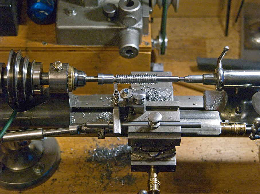
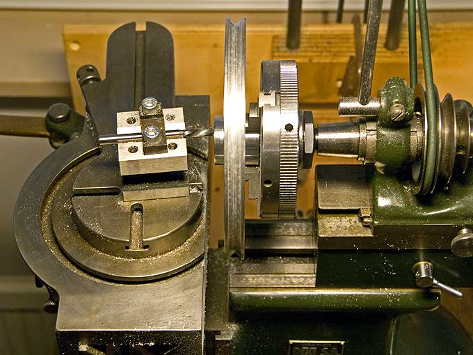
Cutting a new
worm
for the
rotary table
|
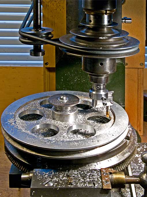
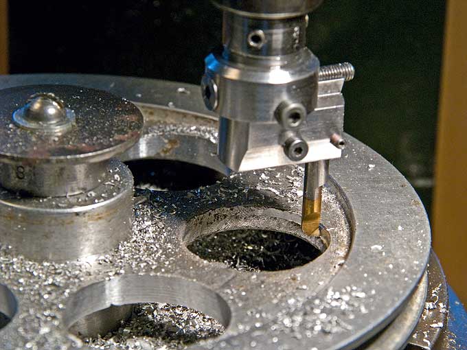
Boring out of
the relieving
holes in the large pulley.
|
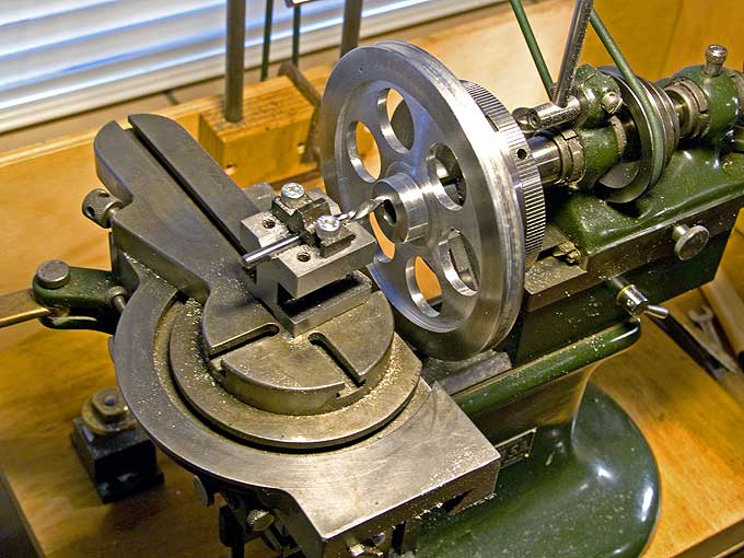
The DIXI mill doubles up
as a facing
lathe for large items. |