|
|
|
|
| From a 1912 Wolf, Jahn & Co. catalogue |
...
and the original |
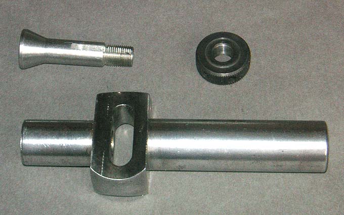
Dissasembled
to show the replacement nut |
updated 03/10/21
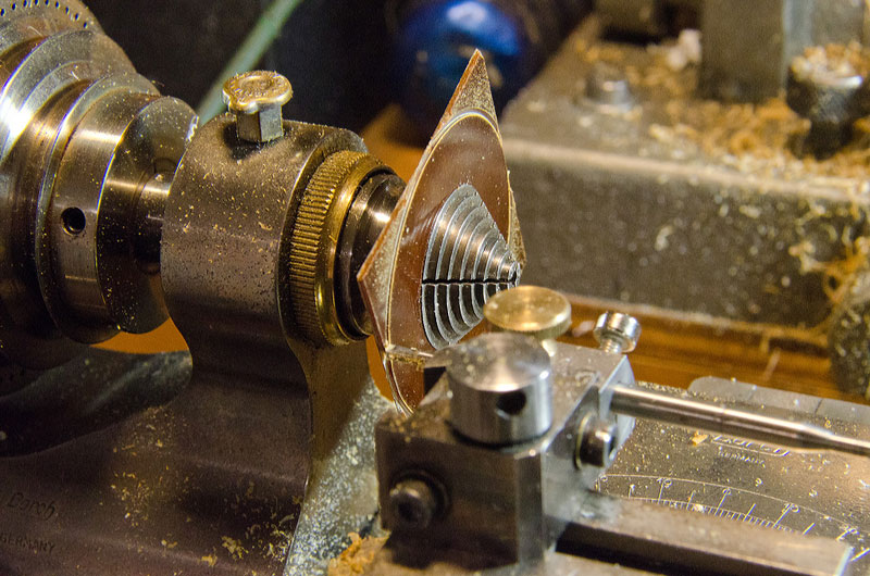
This gadget is shown in the 1912 Wolf, Jahn & Co. catalogue and advertised for the larger larger lathes to go into the three-jaw chuck and hold 8 mm collets for small work. According to Dingler's Polytechnische Journal (1896, Vol. 300, p. 180, http://dingler.culture.hu-berlin.de/article/pj300/ar300043) this gadget was developed by a mechanic Richard Nerrlich in Berlin the tool company Grundmann & Kuhn in Berlin obtained a trade-mark for it. It is equally useful as a hand-held collet holder. I got it with a box of other pieces for WW-lathes. The tightening nut was missing and I have made a new one.
|
|
|
|
| From a 1912 Wolf, Jahn & Co. catalogue |
...
and the original |
Dissasembled
to show the replacement nut |
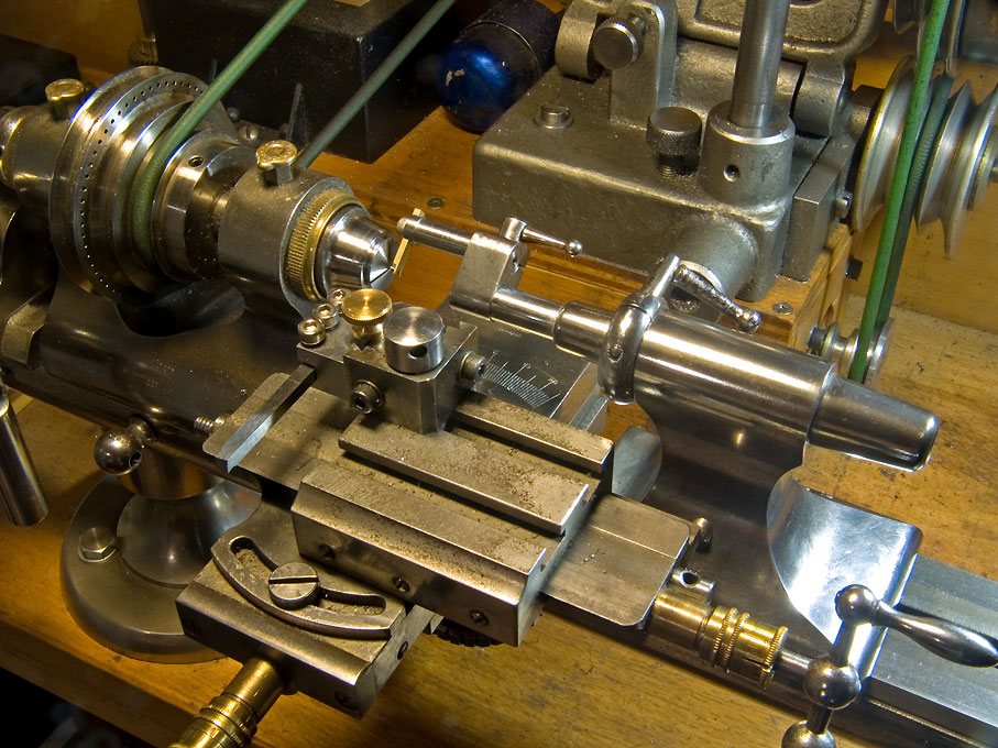
Quick-change tool-posts
tend to be expensive, but useful items. The main body of the
Leinen-made one costed EUR 90 net equivalent according to a 1996
catalogue I have. The inserts would have set you back another
EUR 60 each. So I decided to make my own in 1998,
inspired by the Leinen design. In the late 2010s
the expanding again aftermarket for watchmakers lathe product
was further augmented by sets of small QCTPs
which cost around 150€ for a body with four
inserts.
I actually gave it two dove-tailed slots for normal cutting and
boring respectively, but this is really unnecessary, as I found
that I am turning it anyway to provide clearance etc. Originally, the height-setting knurled nut was locked with a
stop-nut, but I found this design somewhat
cumbersum to handle. After a few years I
replaced the threaded stud with a thumb-screw
and lock the setting with a worm-screw
from underneath. A range of inserts were made for 6/5
mm tool-bits, for 3 mm tool-bits, and for 4 mm round
tool-bits or boring bars. Sleeves for the latter allow
to use smaller diameter tool-bits or boring bars.
If the repeatability of height-setting is all what you need, then there are simpler designs; for instance a round stud clamped into the T-slot and simple slotted holders sliding on it and being tightened down with a compression screw.
 |
|
 |
 |
 |
 |
 |
|
Quick-change tool holder from a 1996 Leinen catalogue. |
Drawing (not to scale) |
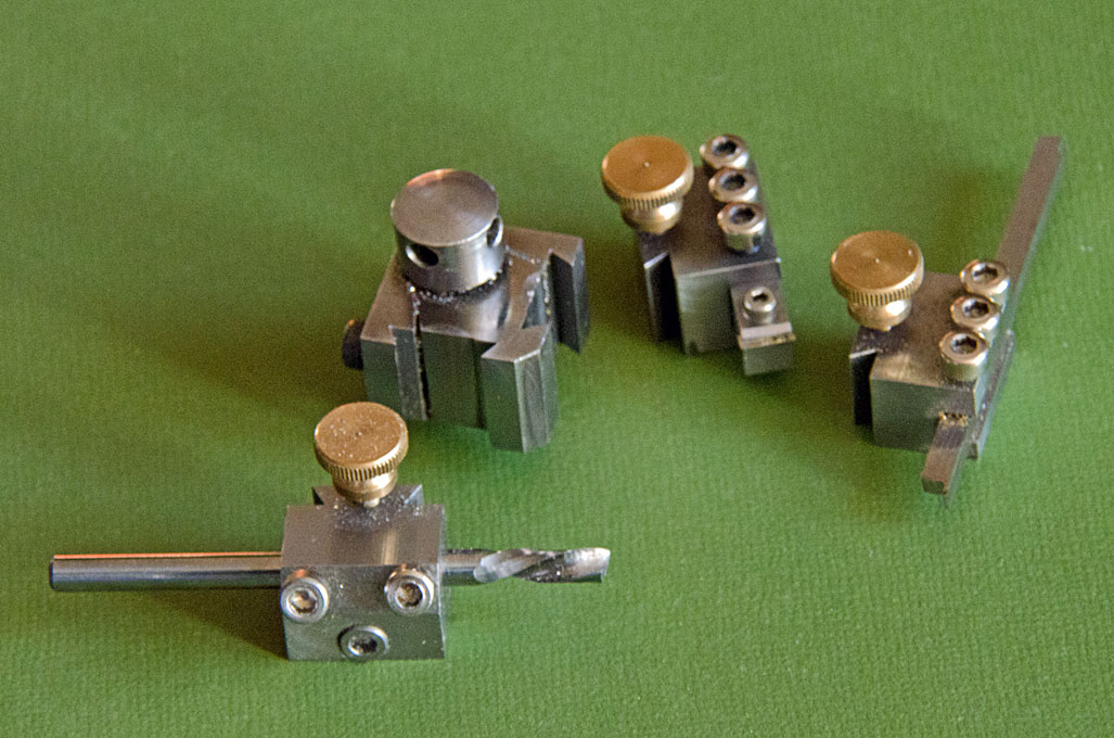
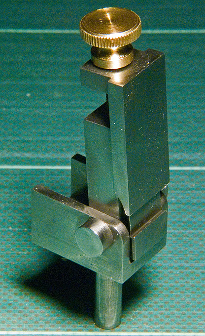
Tool-post and various inserts |
Insert
(right) showing the locking worm-screw |
Insert
mounted |
For
comparison: a traditional lantern- style toolpost; tool height is adjusted with an |
|
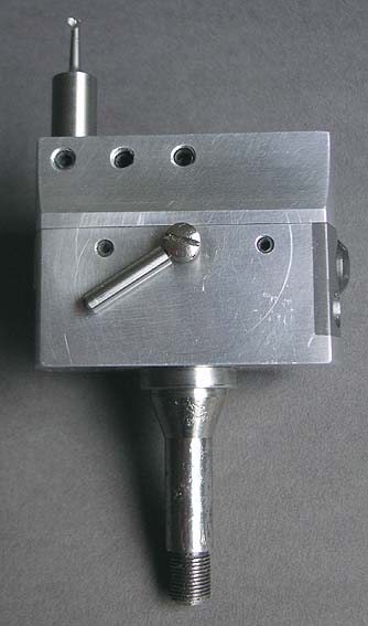
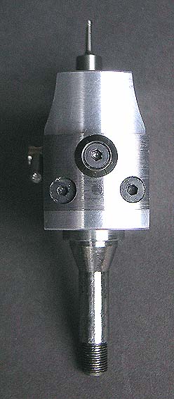
Good boring heads tend to be equally expensive. Also, I wanted one that is not too heavy for use on the small mills and that has not too much off-centre mass when extended. It is made of aluminium and fits onto an 8 mm arbor with a M8 thread. It is bored for 8 mm shank boring bars etc.
|
|
|
|
|
|
Drawing for shop-made |
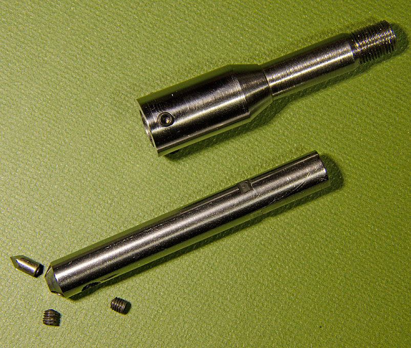
Photographs of the original | ||
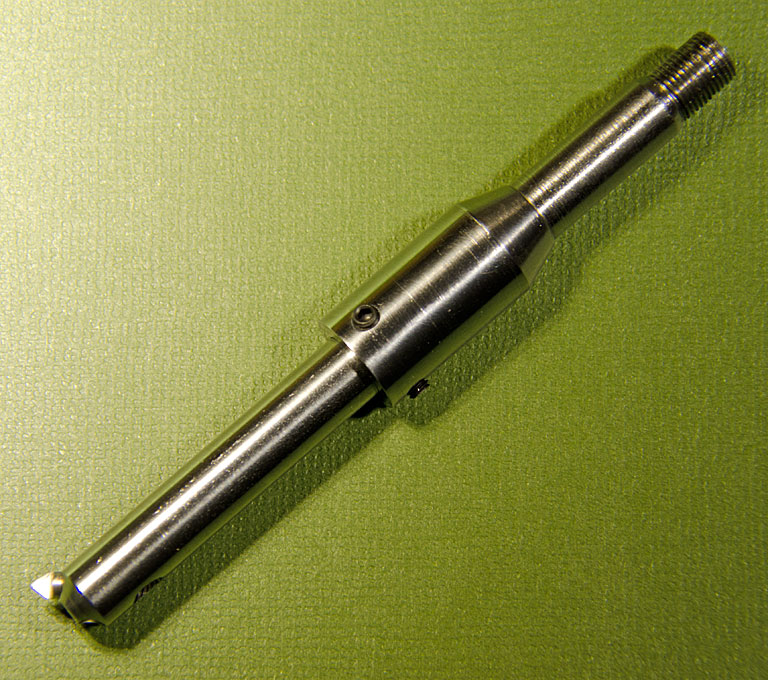
A simple micro-adjustable boring bar was
fashioned from a piece of 8 mm rod. One end was chamfered 3 mm
wide at 45°. Through this chamfer a 2.5 mm through hole was
drilled at the same angle. The hole was tapped M3 for about a
third of the length from above. The other side of the hole then
was enlarged to 3 mm for the cutting tool ground from a short
length of HSS tool-bit. The tool-bit can be pushed out with a
set-screw to increase the cutting diameter in a controlled
fashion. The boring bar is drilled and tapped from the opposite
site of the first hole to take a set-screw for locking the
tool-bit.
 |
|
 |
| Dissambled |
Ready to mount |
In use |
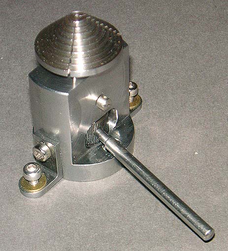
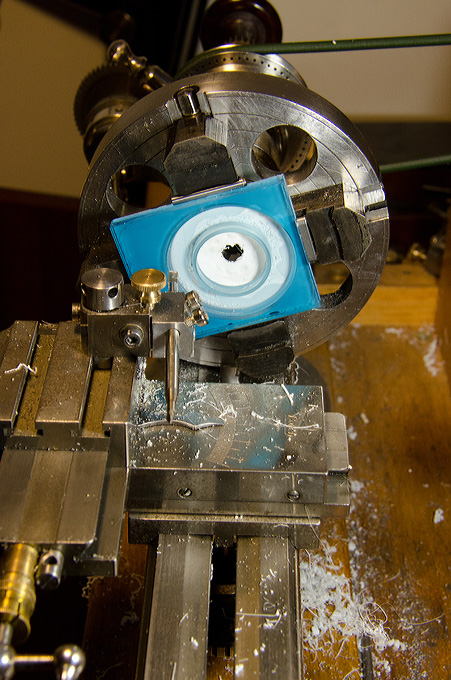
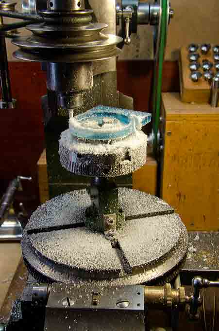
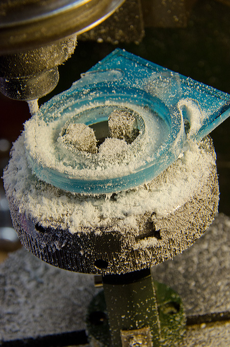
The Wolf,Jahn & Co. Model A milling machine has an integrated rotary table for indexing and it is convenient to hold workpieces upright in a collet or even a chuck. for this pruposes I made a non-indexing collet-holder that can be mounted in the centre of the rotary table. It can take ordinary split collets, wheel chucks, ring-chucks, or even the three-jaw scroll-chuck. The cone on top mimics the spindlenose on the lathe for this purpose. The collets are drawn in by a nut, which can be tightened by a bar.
|
|
|
|
|
|
|
|
| Drawing
for shop-made upright collet holder (not to scale) |
Photographs
of the original (still needs painting) |
Using
various types of collets. Also shown is the
tightening bar. |
The
finished collet holder mounted on the Wolf, Jahn
& Co. miller. Right a six-jaw chuck is held in
it. |
|||
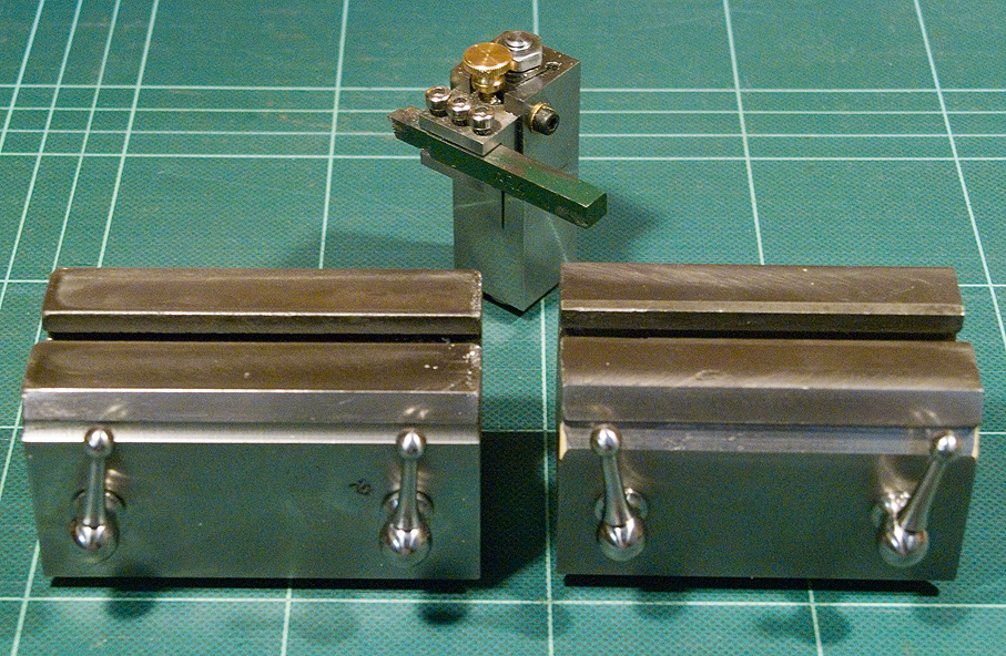
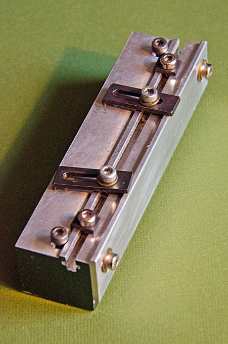
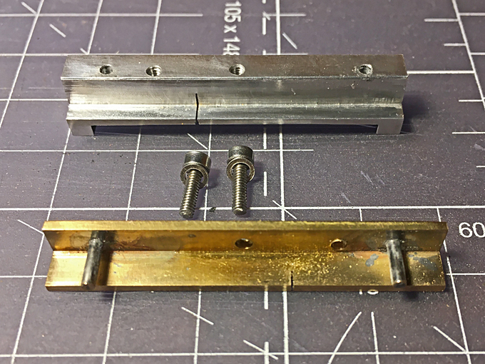
Tilting device for toolmakers vice
 |
 |
 |
 |
 |
 |
 |
 |
 |
 |
 |
 |
 |
 |
| Pultra raising
blocks (picture from www.lathes.co.uk) |
Raising blocks and raised toolpost |
Working on a large pulley |
||
 |
 |
 |
 |
 |
 |
 |
| Miniature tilting and swivelling vice | ||||||
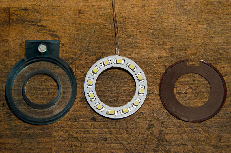
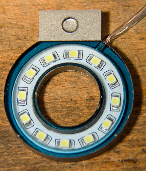
Ring-light for the
vertical milling machine
 |
 |
 |
 |
 |
 |
 |
 |
 |
 |
| Components (body, LED ring, lid) |
Turning the
body |
Shape-milling the lamp body |
Boring the
lid |
Turning the
outside |
Finished lamp |
Lamp mounted |
... and working |
||
 |
 |
 |
 |
 |
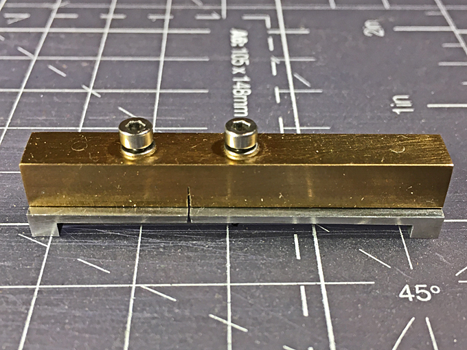
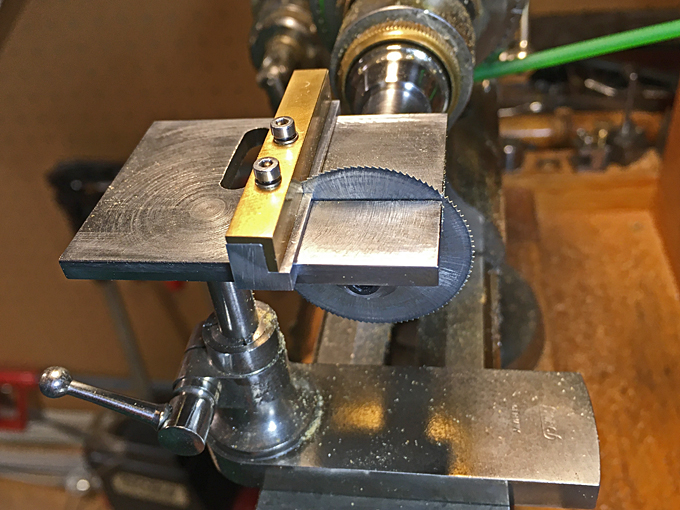
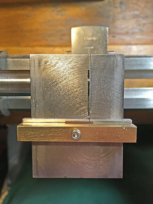
| Hobbing a concave knurling wheel |
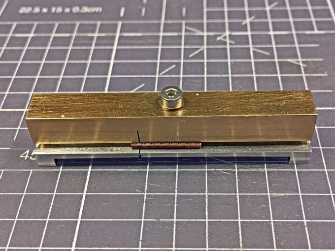
Finished knurl |
Knurl in holder |
Knurling
tool in action |
|
 |
 |
| Clamping device for mill |
|
 |
 |
 |
 |
 |
| Miniature
Cross-Cutting |
Slide for the |
Lathe |
Saw Table | |