first published in autumn 2006 last
updated 12/10/24
Wespe-Class Armoured
Gunboat: The Model
Introductory
Note
Work on this model began in autumn 2006 and then progress with
various long interruption for personal reasons and due to
diversions, such as the construction of tools and machnies
described elsewhere on this Web-site. While you will find below a step-by-step description of
building the model as it progresses,
this is not a continuous 'blog', so watch out for the date on
the beginning of paragraphs to identify new material. For ease
of reference the following table allows to jump to the various sub-sections.
The scale chosen for the
model is 1/160, which admittedly is somewhat unusual for a ship
model. However, the reasoning behind this choice was that a
large selection of N-scale railway figures is available that
eventually will crew the ship. There are also space and
portability consideration, which are important for someone, who
has to move from time to time for professional reasons.
The model will be a waterline model. This will
allow a dioramic presentation of the finished model. Besides,
the hull below the waterline is not quite so graceful. Above
the waterline the hull is also more or less prismatic, with
vertical bulwarks and virtually no sheer. These parameters
together call for a bread-and-butter construction.
The building
drawings are a combination of re-drawn Admiralty plans and scans
thereof. These are printed to scale on the laser printer and the
print-outs glued on top of e.g. the MDF board to serve as a
guidance for cutting and sanding.
Materials
Choice of materials
I had been contemplating a variety of materials for
the hull; for instance Plexiglas®
layers with bulwarks made from brass foil. In the end, I
choose MDF (medium-density fibre) board, which is available in
thicknesses down to 1 mm from architectural model supply
houses. Other parts will be constructed from or covered
with Bristol board, which is also available in various
thicknesses (or rather weights per square metre). The bulwarks
etc.. will be made from Pertinax®
(phenolic resin impregnated paper, FR-2), which is
available in thickness's down to 0.1 mm. Bristol board
and then Pertinax® are easily cut with a scalpel, a razor blade or
scissors and will not crease or dent as metal foil might. I currently have no facilities for photo-etching
large parts, but if I had, perhaps I would have made the
bulwarks from brass still. The other advantage is that
Bristol board can be readily and permanently glued using
white glue. Bonds between large areas of metal foil and Plexiglas® might become detached, though the plating on the steam-tug,
made from copper foil, has lasted now for nearly twenty
years. Pertinax® can be glued using
cyano-acrylate or epoxy-resins. The dinghy of the steam-tug
had received planking made from Pertinax®
and glued with cyano-acrylate glue.
While I have been shying away from thermoplastics,
such as polystyrene, on account of it being suspicious to be
not 'permanent' (e.g. the articles
by
Dana Wegner), practical experience shows that plastic
models built over 35 years are still intact. So I may
reconsider my position in this respect. Polystyrene, of
course, has several advantageous properties.
Some thoughts on Etched
Parts
Some people refer to the process of making
photo-etched parts as chemical milling and that is the way I
view it; a process to cut out and shape parts that are too
small or otherwise to delicate to handle conveniently with
other manufacturing processes. Unfortunately, the employment
of this process moves much of the modelling work onto the
computer, as the patterns or masks now are produced with the
help of a drafting program. These masks are largely developed
by scaling the contemporary drawings and drawing the
respective part over it in a different layer. These parts are
then composed into the actual mask. Of course, 'left' and
'right' sides have to be drawn separately, if the part is to
receive surface-etched detail. A strict procedure of copying
and mirroring has to be adhered to in order to achieve a
perfect line-up. Much thinking has to go into the best shape
of parts and some experimentation. The etching process is not
so well controllable, as a machine tool, at least in the
simple set-up I am using. The best thickness of interlocking
slots or the drawing size to achieve cut-outs of a specific
dimension and similar features have to be found by trial and
errors sometimes. Literary it is often 'back to the drawing
board'.
This set-up is only suitable for dip-etching.
Commercial companies use foam or spray etching, which work
faster and produce less undercut. I decided to work with very
small 'frets' only, the size of one or two large stamps. This
reduces the cost of material, if something goes wrong and the
smaller size seems to make it easier to get uniform results
over the whole 'fret'. I bought second hand a UV-source for
exposing printed circuit board. It has a timer and hence makes
the process more repeatable. The developing and etching
vessels are plastic film tins, coming from the standard film
rolls (don't get any new ones since I have switched to
digital, of course). The brass is bought in a ready-sensitised
state, so no messing about with UV-sensitive lacquer is
needed. Much experimentation went into a suitable way of
making the masks. Eventually a newly bought ink-jet printer
produced sufficiently uniform print-outs on overhead foil, but
the resulting masks are not really perfect. However, I did not
want to go a commercial photo lithography company for them.
The hull and
superstructures
Autumn 2006 - The
basic bread-and-butter construction of the hull is shown in
the pictures above.
The Barbette mainly consists of a semi-circular breastwork
armour, backed by hardwood and by an open space covered with
thin plate. The latter presumably to retain splintering wood
in case of an impact. Since no tube of suitable dimensions for
the breastwork was to hand, I made a short laminated one from
Bristol board glued together with white glue. The edges were
soaked in thinned white glue before being trimmed down on the
lathe. The tube then was varnished with filler for wood before the edges
were sanded. Finally a half-circle was cut from the tube on
the jig-saw. More wood-filler was applied before final
sanding. After cutting in half it was glued into place. The
inside of the barbette was lined with hard-paper to give a
smooth finish.
The fore-deck has been covered in a sheet of thin Bristol
board and the camber of the wooden decking built up with an
additional piece of board and putty (I am using fast drying
bodywork putty from car repair suppliers). The anchor pockets
have also been lined with thin Bristol board, but Pertinax
would have been better for this.
All surfaces that would have been iron plating, will be
covered in thin sheets of Pertinax. The necessary holes for
portholes and other opening will be drilled or cut before the
sheets are fixed. In this way the barbette was lined with sheets
of Pertinax,
as was
the deck-house.
Cutting the layers on a
powered fretsaw
Sanding the
sides of each layer vertical on an improvised disc
sander
The first
layers
The barbette
and pockets for the anchors cut out
Milling
slots for the rubbing strakes
Improvised
drum
sander to work the inside of the barbette
Shaping
the body on the new shop-made disc sander
Tube
made from laminated Bristol board
Trimming
tube
on the lathe
Drilling the hawse pipe
on the horizontal milling machine
Deckhouse partially
clad in Pertinax
January 2017
Most of the decks were plated and this plating
was covered in oil-paint that was mixed with sand and cement
in order to provide a certain corrosion resistance and above
all a better grip in wet conditions. A modelling
plan drawn by Wolfgang Bohlayer shows wood on some
decks, but evidence that since has become available shows that
this was not the case.
Linoleum decking
apparently was never used on these boats. However, as the model
will show the boat in its original appearence, the plating was
reproduced by engraving fine lines into then sheets of Pertinax.
All decks, including that of the barbette will covered in this
way. The exception is the deck above the foc'sle that a cover in
planks, presumably to reduce wear, where the anchors were
worked. This planking was laid-out in a radiant pattern, which
seems to have been more resistant to the gun-blast than the more
common parallel layout. The planks were also reproduced by
lightly engraving the plank seams. In reality these seams would
have been more or less flush with the deck, depending on the
temperature and humidity, but a light engraving adds some life
to the appearance.
Progress in
constructing the hull
Engraving
plating and planking
Excerpts
from contemporary drawings
Barbette
Toner-trasnfer printing of
bulwark layout
The
barbette - The floor of the barhette is partially covered
in planking, presumably to protect the armour-steel deck
underneath from the damage that might occur, when the heavy
shells are handled. The steel deck underneath and in front of
the barbette armour-belt is slightly sloping to deflect incoming
enemy-shells from the ammunition storage-rooms. Within the
barbette this is filled with timber to make a level floor. The
interpretation of the various items that can be seen in the
contemporary drawings is not straightforward. However, one can
see a hatch that gives access to the crew's quarters (where also
the hand-cranks for turning the gun-carriage is located). Then
there is a round hatch for hoisting up the charges from the
powder-locker below and a square hatch for hoisting up the
shells. From the drawings it appears that these hatches were
covered in steel-gratings. There is a further hatch with a
double-lid that, according to a hand-written notice on one drawing
is a man-hole leading
to the ante-room of the shell-locker. However, as it is not
drawn in the cross-sections we do not know its height. There are
also a couple of racks for shells and some other rack-like
features, the purpose of which I do not know - perhaps for tools
needed in handling the shells. Unfortunately, there are no
photographic images that show the rear of the barbette.
Stairs leads down from the bridge into the barbette. In addition
two ladders allow quick access from the deck.
The
floor of the barbette, which apparently did not have any camber,
was built up from two layers of Pertinax one representing the
steel-plating and engraved accordingly, the second cut out and
engraved to represent the wooden flooring. The construction of
the various hatches is described below.
Bulwarks,
hull- and deck-plating installed
Making
and installing the hawse-pipes
Scraper
for half-round profiles
Rails and
rubbing strakes installed
Toilet evacuation pipes
Milling the steps of
jacobs-ladders
May 2019
- The main-deck plating, which had already been prepared a long
time ago from a piece of bakelite (see above). The holes for the
various fittings where marked out over a drawing and then
drilled. The translucent property of the bakelite is very
helpful for marking out. Once glued on, the deck was carefully
sanded to the contour of the hull.
I spent a lot of time deliberating the best way to make the
plating of the hull and the bulwark. The shape is quite simple,
as the sides are vertical from just below the waterline
(probably to facilitate the production of the armour plating
that needed to be curved in only one direction). The original
idea was to cut the plating in one piece from brass shim stock.
This would have resulted in near scale thickness of the bulwark
plating. I considered this too flimsy, even if the handrail was
soldered on. Another option would have been to use 0.13 mm
styrene sheet. Again I considered it too soft. Bakelite sheet of
0.1 mm thickness would have been closer to scale, but rather
brittle. For practical reasons I decided to use 0.2 mm bakelite
sheet.
The layout of the freeing ports, the location of stanchions, the
ash chutes, toilet drain pipes, and port-holes were drawn onto
an expansion of the bulwark that was developed from the original
drawings. The drawing then was laser-printed onto an overhead
projection foil (remeber these ?). This foil was taped to a
piece of bakelite sheet and the drawing ironed onto it, using
what is called the toner-transfer method.
The plating was cemented to the MDF hull using cyanoacrylate
glue (CA). I am not very fond of CA glue, but it forms secure
bonds with bakelite. On the prototype, the
bulwark plating was attached to the hull by an angle iron (8
cm x 8 cm) running along the top of the hull. I simulated the
vertical part with a 0.5 mm wide strip of self-adhesive
aluminium sheet into which a row of rivets had been embossed.
The horizontal part would disappear under a thick layer of
tar-based paint that was mixed with sand and onto which sand
was dusted to provide a non-slip deck.
The hawse pipes were made from
some 2 mm x 0.5 mm brass tube. First the angle with the hull
was cut and then an oval ring from 0.4 mm copper wire was
soldered onto this surface. The part was then taken into a
collet on the watchmakers lathe and drilled out to 1.7 mm ID.
Finally, the funnel shape was formed with diamond burrs and
polished with silicone burrs. The hawse-pioe then was cemented
in place and the end above the deck ground down in situ flush with
the deck. The cover on deck is an etched part I made already
several years ago. It was cemented on using CA and then
another funnel was shaped with diamond and silicone burrs.
Next step was to install at the bows the fairleads for mooring
cables etc. These were milled and filed from 0.8 mm thick sheet
of Plexiglas®.
Then the rails on the bulwark in the rear part of the ship were
installed. The rail also serves as a rubbing strake and
continues to the anchor-pocket at the bows. At first the bulwark
and rail (0.4 mm x 1.7 mm on the model) caused some
head-scratching and concerns for the stability of the
arrangement. I though about cutting a longitudinal slot into
some rectangular styrne, but finally decided to make it in two,
with the half glued inside and outside to the bulwark that have
been designed higher for the purpose. In this way a 0.4 mm x 0.7
mm styrene strip could be glued all the way to the outside of
the hull. A similar strip was glued to the inside. The
half-round profile was shaped using a scraper made from a piece
of razor-blade and held in pin-vice. The profile was shaped
after attaching it to the hull, because it was easier to clamp
the rectangular styrene strip while glueing. The glueing was
effected by infiltrating CA into the joint between the styrene
strip and the bakelite bulwark.
Arrangements varied somewhat between the different boats of the
WESPE-class, but there was a WC for the officers in the
deckshouse on the starbord side and a WC and pissoir for the men
and petty officers on the port side. Each had a half-round
evacuation pipe rivetted to the outside of the hull. The pipes
were protected against damage by a wooden fender. After a few
years of service, a strong wale/rubbing strake was added to the
boats that also widened to a kind of sponson at the stern to
protect the screws. However, this did not exist at the time in
which the model is represented.
Steps
ready to be installed
Jacob-ladders
Fairlead
for mooring hawser
Laser-cut lids
for the freeing-ports
Installation
of frames and lids
Laser-cut
doors
Decks-house and back of
the fore-deck with the doors installed
June 2019 -
There are two jacob-ladders on each side of the hull, a wider
one underneath the door in the bulwark and a narrower one a bit
forward. The steps probably were made from wood and had slots
towards the hull to prevent the water from collecting there and
to prevent the wood from rotting. The steps are made from 0.8 mm
thick Plexiglas® and the slots milled in. The sheet then was
sanded down to the width of the steps and the ends rounded. Then
individual steps of the right thickness were cut off on the
lathe set-up with a mini saw-table. Unfortunately, the steps
could only be cemented to the hull using cyanoacrylate glue,
there being no positive locking. A bit of cellotape provided a
guide for alignment. Nevertheless, the procedure was a bit
nerve-racking.
Further, fairleads for the aft mooring hawser were installed.
These were made from oval rings of copper-wire. The rings were
formed over two 1 mm-drills taped together, cut off and closed
by silver-soldering. The rings were sanded down to half their
thickness and one each of these rings cemented to the inside and
outside of the hull. The hole was drilled out and filed to
shape. February
2020 -Freeing
Ports - Originally
I had planned to surface-etch the lids and the frames on the
inside of the bulwark. The drawings for the masks were ready,
but I never got around to actually etch or have the parts
etched. Since I now have the laser-cutter, these parts were
cut from printer-paper (80 g/m2 = 0.1 mm thick). With a width
of the frames of only 0.5 mm, the surface-etched rivets may
not have come out anyway. The same for the rivets on the
hinges of the lids. At least not with my somewhat primitve
home-etching arrangement. If I had etched the parts from 0.1
mm nickel-brass, the overall thickness would have been reduced
to a more correct 0.05 mm (= 8 mm for the prototype) The lids have no latches to lock them and the
ports no bars across them to prevent items or people being
washed over board. This makes their construction simpler.
Papers, even the
smoothest ones, alway have a certain surface-roughness, at
least compared to the bakelite of the bulwark. Therefore,
the chosen paper was soaked in wood filler and spread to dry
on a thick glass-plate that was covered in cling-film. The
latter allowed to remove the paper without it rolling up.
The surface was then smoothed with very fine steel-wool. The
lids were cut from the thus prepared paper, but it needed
several trials to find the right cutting parameters in order
to arrive at parts of the correct dimensions. This is a
disadvantage of such simple laser-cutters and their
software. As the material is practically free, this is only
a nuisance, but no other loss. Also the etching may not work
out right in the first go, which may mean a considerable
loss of money and time, if the process had been outsourced-
Unfortunately, it does not work for very small parts with
the paper prepared as above. It turned out to better for the
very small parts, including the frames, to cut them from
unprepared paper. Perhaps I should switch to dark paper. Due
to its lower albedo (reflectivity) it absorbs more energy
from the laser. Unfortunately, all the coloured papers I
have come by so far are quite rough on the surface.
I cheated somewhat for the freeing-ports. As I was afraid
that I would not been able to cut them out cleanly and
evenly, I abstained from it. Also, the bakelite-paper used
for the bulwark for reasons of stability would have had a
scale-thickness of 64 mm, when looked on from the side.
Therefore, frames and lids were glued flat onto the inside
and outside of the bulwark respectively. I hope one will not
notice this too much, once the stanchions are in as well.
Frames and lids were glued on with zapon-lacquer. Little
laser-cut rectangles of 0.3 mm x 0.5 mm were stuck onto lids
to simulate the hinges.
Foredeck and decks-house were accessible through various
doors. These were cut from 0.1 mm bakelite paper with the
laser-cutter. The hinges were laser-cut from thin paper. In
both cases various tries were needed with different cutting
parameters and slightly altered drawings in order to arrive at
the correct size. Die parts were assembled using
zapon-lacquer. Zapon-lacquer was also used to glue the door
into place.
On historical photographs I noticed that each door had a
narrow step. These were represented by shaped and laser-cut
tiny strips of paper.
Once the door were in place the hole for the bullseyes were
drilled out. The laser-cut hole served as a guide. Once the
boat is painted, the glazing will be installed in form of
short lengths of 1 mm Plexiglas rods. The front of the rods
will be faced and polished carefully on the lathe.
At a later moment also the door-knobs will be turned from
brass and installed.
Best
available image of the bow scrollwork and name-plate
(S.M.S. SCORPION)
Only
available image of the stern scrollwork (S.M.S.
NATTER)
Artwork for the
bow scrollwork
Some
examples of (unused) laser-cut scrollwork and
the name-plates
Scrollwork and
name-plate in place
Stern
scrollwork in place
June 2020 - Scrollwork and
name-plates - As I had tried laser-engraving on
cardboard for the gun-layer stand, I wanted to try out this
technique also for the scrollwork and the name-plates.
Originally, I had foreseen to develop the scrollwork by
printing the design onto a decal-sheet and then build it up by
sculpting it over the printed lines with acrylic gel. The
name-plates could have been surface-etched in brass. One could
have etched, of course also the scrollwork in brass and then
complete it with acrylic gel.
It is not very clear what the scrollwork looked like when new
and from what material it was made. The fact that it seems to
have persisted intact over the whole life of these ships may
indicate that it was actually cast in some metal, rather than
carved in wood.
There are no close-up photographs of sufficient resolution in
the black-white-yellow paint-scheme. Closer photographs are
only available from a later period, when everything was
painted over in grey and some of scrollwork may have been
picked out in a darker grey. Originally it was probably
painted in yellow-ochre with parts of gilded. In any case,
available photographs are not clear enough to truly
reconstract the scrollwork, so some interpretation was
necessary.
In addition to the scrollwork per se, there was a shallow
sculpture of the animal after which the ship was named, for
SMS WESPE, of course, a wasp. Existing photographs only give a
vague idea what these sculptures really looked like. In any
case not for SMS WESPE.
There has also been some scrollwork at the stern, but
pictorial evidence for this is rather scarce. There is only
one known photograph that gives a full view of the stern of
this class of ships and this was taken at the very end of
their service life. Available copies of this photograph are
not clear enough to really discern what the scrollwork
actually looked like, so a fair amount of imagination is
needed to recreate it.
Creating the basic artwork for the decoration was a
multiple-step process. First a photograph of the respective
section of the model as built was taken in order to give the
necessary proportions. In the next step the best available
photograph with the least perspective distortions was chosen
and fitted over the model photograph. In another layer of the
graphics software (Graphic for iPad) the scrolls were drawn
free-hand (with the iPen) using the paintbrush-function and a
good amount of smoothing. This artwork was saved as a JPEG. On
the Internet I found a nice drawing of a wasp and turned this
into a pure b/w image with a good bit of editing in Photoshop.
Both, the scrollwork and the wasp were saved as transparent
GIF. In my favourite CAD-program (EazyDraw), the parts were
mounted together. This could have been done also in Photoshop,
but I did have a scaled drawing of the bow-section in EazyDraw
to which I exactly fitted the artwork. There were also some
addtional parts to be cut.
The scrollwork was cut/engraved with the laser-cutter using
the ‘half-tone’ function, which means that the laser is
modulated to emit less power when a grey pixel is encountered
and full power, when a black pixel is encountered. I had to
play in several iterations with the settings of the
laser-cutter in order to arrive at a satisfactory result.
In a first try the name-boards were made in the same way, but
the half-depth engraving around the letters resulted in a
somewhat fuzzy apearance of the letters. I, therefore, tried
out a different idea. From previous trials it was know that
the laser had no effect on transparent materials and very
limited effect on translucent materials. Hence, I covered some
cardboard with a thin layer of Pleximon 192 (essentially
liquid, light-hardening Plexiglas). A thorough curing this
sandwich was sanded flat and presented to the laser-cutter.
The laser removes all the cardboard, but leaves the acrylic
virtually untouched, with the exception of some light surface
roughness. One ends up with a piece of thin acrylic sheet to
which the letters and the scrollwork of the name-board are
attached. Within the limits of the resolution (0.05 mm) of the
laser-cutter the lettering turned out reasonably clear,
perhaps not as crisp, as when photoetched though.
The scrollwork elements were attached to the hull using
fast-drying varnish. The actual painting and guilding will be
done, once the hull has been painted.
The
aft part of a WESPE-Class-Boat (Lavverenz, 1900)
Etched
and soldered together stanchions (they are about 5.5
mm high)
The bulwark-stanchions in
place
Recessed
slide and anchor release gear
Recessed slide with
Inglefied-anchor put temporarily in place
View of
the bow with the anchor stowage
Plexiglas plugs
ready for insertion
Glazed portholes
Glazed portholes
December 2020 - bulwark stanchions - The bulwark in the
aft part of the hull is supported by a number of stanchions that
were cut from sheet metal and rivetted together. The looks for
these stanchions is reasonably well documented on a number of
photographs.
The stanchions I had drawn
already years ago and depicted the rivetting by
surface-etching. The material is 0.1 mm thick nickel silver.
They were made in double as mirror images and soft-soldered
together in pairs with soldering paste so that the rivetting
appears on both sides. The location of the stanchions
was marked on the bulwark before this was put into place by
thermo-transfer of a drawing, i.e. a laserprinter printout was
ironed on. The stanchions were cemented in place with
fast-dryining varnish.
Already a short while ago I had fashioned
the boiler-ash chutes by milling to shape little blocks of
acrylic glass. They were cemented to the bulwark inside and
outside at this stage too. January
2021 - Anchor stowage and release gear - The
Inglefield-anchors are stored on sort of recessed slides and
released by a traditional form of gear. This gear consists of a
rotatable iron bar with a couple of thumbs welded on over which
the securing chains are hooked. The chains go around the anchor
and the other end is shackled to the wall of the recess. The bar
is prevented from rotating by lever that is also welded to it.
The lever in turn is locked by a rotating claw at the end of a
second lever. I suspected this mechanism from the available
drawings, but wasn’t shure about it – a German colleague had
better eyes than me an could confirm this indeed on the not very
clear photographs.
The slide is protected by three T-rails on each from the weight
of the heavy anchors.
The release gear was fabricated from 0.3 mm diameter tinned
copper wire and assembled using varnish. The rails in turn are
fabricated from laser-cut strips of Canson-paper that was soaked
in varnish. They also function as bearing for the bar of the
release gear. I suspect the bearings were a bit more elaborate
on the prototype, but I don’t have more detailed information.
The locking claw is also a microscopic laser-cut piece. As
usual, I had to experiment with different variants of the
drawings and settings of the laser-cutter until I managed to
produce reasonably clean parts. December 2021 - Porthole Glazing - Following the
discussion on ways to make the porthole glazing further up, I
looked over all available photographs and came to the conclusion
that one does not actually seem to see the bronze frame from the
outside. On the other hand, most photographs or their scans do
not have sufficient resolution to really see such detail.
In order to make my life simpler, I decided to go for solid
Plexiglas plugs. I did have 1 mm Plexiglas rod in stock and
short sections were cut from this to make 2 mm long plugs. The
plugs have to be a bit longer than their diameter, so that they
can be inserted straight. The front face was turned flat on the
lathe and the back-end was given a bit of a chamfer for easy
entry into the pre-drilled holes after which it was painted
black using a black permanent marker pen. The pieces were then
transferred to the micro-mill for polishing the front face with
a silicon rubber polishing bit.
In order ensure that the porthole plugs are set at equal depth,
a little ‘tool’ was made, a punch with a recess of 0.3 mm depth
around the rim.
The 30.5 cm Rk/l22 gun
Lower Carriage
February 2007 -
There are some fixtures for the gun that need to go into their
place in the barbette early during the construction, including
the races for the gun carriage and the semi-circular toothed
rack that is part of the gun-training machinery. I decided to
make these from steel, even though ferrous metals in model
construction are frowned upon by museums. My justifications were
that it is difficult to represent cast iron or steel by paint
and that there hundreds of models in museums around the world
that contain iron. I have used steel it in models some twenty
years ago and presumably due to the lacquering shows no signs of
rust.
Cutting thin disks from round stock of sizeable diameter is a
pain I wanted to avoid. Against my better knowledge I picked a
suitably sized steel washer as starting material. Unfortunately,
the steel used does not cut very well at all and lot effort was
spent to avoid chatter marks while turning and to obtain a
reasonably good finish. The various types of wheel collets
available for the watchmaking lathe come into good use for
working on inside and outside diameters of the disks.
I set up the
hand-shaper for cutting the rack teeth, but had to throw away
the first two attempts because of the poor material and because
- again against better knowledge - I did not lock the traverse
slide when cutting. The table was removed from the shaper and
the home-made dividing head bolted on instead. For lack of a
proper tool grinder (another project) I hand-ground a cutter for
the rack tooth (0.1 mm at the bottom) from a rod of high-speed
steel. For holding this tool-bit in the shaper, the old
lantern-style tool holder from the watch lathe came very handy.
The unwanted parts of the ring were cut away on the shaper using
ordinary left and right hand lathe tools. Finally the necessary
sections were trimmed off with a fine saw blade on the lathe's
sawing table.
Roughing out the metal
disk with the backing of a wooden disk
Grooving the
races with a specially ground bit
Cutting out
the inside of the large, backward ring
Trimming the
outside of the small, forward ring
Shaper
set-up
for cutting the toothed rack
Cutting
the
toothed rack with a specially ground tool
Cutting
away
the unwanted part of the ring with an ordinary
tool
The
set-up showing the finished rack
The
races and the toothed rack ready to be trimmed
to correct length of arc
Base-plate
and rails for upper carriage laser-cut from
Canson-paper
The
basic frame of the lower carriage from the
rear
February 2020 - The
lower carriage of the gun was a rather complex construction
from rolled L-profiles and thick steel sheet. Unfortunately
only the drawings in GALSTER (1885) and the coloured synoptic
drawing from the Admiralty have come to us. Many construction
details are superimposed onto each other with dashed lines, so
that the interpretation of the drawings is rather difficult in
places. As aids to interpretation with have one close-up
photograph, the large demonstration model in the navy museum
in Copenhagen, and the preserved guns of Suomenlinna Fortress
off Helsinki. The carriage for the Danish iron-clad HELGOLAND,
however, differs from that of SMS WESPE in some details, being
actually a turret-carriage. The carriages in Suomenlinna are
Russian copies of Krupp fortress carriages, but they allow to
verify certain construction details that are not clear from
the drawings.
Originally I had planned to construct the lower carriage,
like the upper carriage, from surface-etched brass parts. To
this end I produced some time ago already the needed detail
drawings. Surface etching is a very good process to simulate
rivetting. In the meantime, however, I had purchased the
laser-cutter, so that laser-cut parts would be an alternative. I
had hoped to cut the parts from bakelite paper. Various trials
with different cutting parameters unfortunately were not very
successfull for the intricate parts. The 5 W laser ist too weak
to burn the material fast enough. Burrs of molten and partially
carbonised resin form. Therefore, I fell back onto Canson-paper,
which is a bit over scale with its thickness of 0.15 mm.
The
drawings for the etching masks had to be reworked for laser
cutting. It turned out during assembly that I had made several
mistakes or misinterpretations. If I had send them off for
etching this would have been costly, as both masks and etching
would have to be redone. When cutting paper with a laser such
corrections can be made quickly and easily – and the material
costs practically nothing.
The laser-cut parts were soaked in nitrocellulose wood-filler
and once dry rubbed with very fine steel wool. To double up
parts and for assembly zapon lacquer was used. This dries so
fast that no special arrangements for fixing the parts are
needed.
I did not take pictures of the different steps of assembly, as
this would have rather impeded the process. First all parts to
be doubled up were cemented together using zapon lacquer and
weighed down to keep them flat during drying. The longitudinal
parts of the carriage had slots cut into them, so that the
transveral parts could be positioned exactly. The frame assembly
then was cemented to the base plate (which in reality was not a
plate, but rather the frame was put together from L-profiles and
steel sheets). The racers, again in one piece, where glued on
top of this assembly. Underneath the base plate the housing for
the training gears (which will be very much simplified as they
will be barely visible upon completion of the model).
One can see on the laser-cut parts marks for the rivets. These
will be added as tiny spots of white glue. More details will be
added in the next steps, but have not all been drawn yet.
The basic
frame of the lower carriage from the rear
The basic frame
of the lower carriage from underneath with the
housing for the training gears
The
basis frame of the lower carriage with the upper
carriage and the gun put temporarily in place
Working
drawing for the parts of the hydraulic brake
The
individual parts of the hydraulic recoil-brake
Dry-fitting of the recoil-brake into
the lower carriage frame
Buffer
beams on the lower carriage
One buffer dry-mounted
March 2020 - The 30.5 cm
gun in pivot-carriage C/76 was one of the first guns in the
Imperial German Navy that was fitted with a hydraulic
recoil-brake, at a time, when compressors and brooks were still
the standard.
The recoil-brake consists of a long cylinder with
screwed-on cylinder-covers at both ends. The covers are pierced
for piston rods and are sealed with packed glands. The piston
rods are fixed at the front and rear end of the carriage
respectivly. The piston is designed as self-opening one-way
valve. The cylinder is filled with glycerine through a valve on
top. The front-end cylinder covers acts also as cross-head and
the upper carriage is linked up through two short forked
connecting rods. The cross-head runs on a kind of slide to
support the weight of the brake. The two piston-rods are only
connected by the short piston, which also acts as valve, and
that would not be able to support the weight.
When the gun is fired, the upper carriage slides back and the
piston is pushed through the glycerine, converting the kinetic
energy of the recoil into heat. The valve in the piston prevents
the upper carriage from sliding back into firing position. In
order to bring the gun forward, the rear end of the carriage is
raised by turning the excentric bearings of the rear wheels and
opening the valve in the piston. To facilitate this, the rear
piston rod is hollow and a spring-loaded valve-rod extends
beyond the piston-rod. The valve rod can be srcewed in and out
by the aiming gunner using a long lever. In this way he can let
the gun roll back into the firing position in a controlled way.
Unfortunately, not much of the hydraulic brake will be visible
on the finished model, so that it was reproduced in a somewhat
simplified way. It consists of five parts.
The piston rods were fashioned from clothes pins of 0.6 mm and
0.7 mm diameter respectively. Clothes pins are very suitable for
piston rods, as they have a nicely polished surface. The eye of
front piston rod was milled/filed from the head of the clothes
pin.
The cylinder was turned in one piece together with the covers
from a short length of 2.5 mm round steel. On the micro-mill a
hole was cross-drilled for another short piece of steel that had
the cross-head pins turned on. This piece was soft-soldered into
the cylinder cover. The packed gland is compressed by a
hexagonal nut, for which the hexagon was milled on in the
dividing head in the same set-up.
The forked connecting links were laser-cut from paper and
consist of three pieces each. The bronze
housing for the valve spring was turned from 1 mm brass rod. The valve lever will be added at a later
point.
Buffers and
fastening nuts
Buffers and
fastening nuts – the buffer have a diameter of 1
mm
Safety
claw, pivot plate and drive shaft
Milling the loading
crane
Fork for pulley
Milling
the pinion and cog-wheel for the winding
mechanisms
Part-assembled
loading crane
Buffer beams - In
order to limit the recoil and the running out of the gun,
buffer beams are installed at both ends of the frame of the
lower carriage. Each beam carries four buffers against which
the front cross-beam of the upper carriage runs. The buffers
are designed as pistons with piston rods screwed to the back
of the beam. It is not completely clear what the elastic
elements were. The drawings seem to indicate rubber discs with
metal separating discs. On some of the guns at Suomenlinna
fortress there are remains of rubber discs, while the
demonstration model of the Danish navy seems to have spiral
springs.
The bodies of the buffers were turned from 1 mm soft steel
wire. The spring element was simulated by winding around it
several turns of 0.15 mm tinned copper wire. Whether this is
meant to meant to represent rubber discs or springs I will
decide, when it comes to the painting stage.
The nuts that keep the buffers to the beam were also turned
from 1 mm soft steel wire. First, the hexagon for a 0.6 mm
spanner width was milled on in the dividing head of the
micro-mill. On the lathe a 0.4 mm hole was drilled and 0.3 mm
long nuts parted off. And no, I didn’t cut a 0.4 mm thread.
The parts of the buffer beams were laser-cut from 0.15 mm
thick Canson paper and soaked in wood-sealer. They were folded
and assembled using zapon varnish. In order to make folding
more precise, a row of tiny holes were ‘punched’ along the
folding lines with the laser-cutter, which weakens the
material there. The rivetting was simulated by tiny drops of
acrylic gel that was applied with a syringe and a fine
injection needle. The needle was ground flat at the end for
this purpose. Safety claws - A heavy forged claw at each end of the
frame hooks under the rail on which the carriage trucks run to
prevent the carriage from lifting off the pivot. The profile
of the hooks was taken off the original drawings and cut in
multiple copies from Canson paper. These were glued together
as a stack and sanded smooth – not a 100% satisfying solution,
but filing such tiny but wide claws from the solid I found too
fiddly. The lugs that attach the claws to the frame were also
cut from Canson paper.
The gun is trained with the aid of a curved rack, a
crown-wheel segment in fact. In to this rack made from bronze,
a steel pinion engages that is driven by a shaft from a sort
differential, which is powered by man-power from the deck
below the barbette. After some consideration I decided not to
make the pinion, though I would have liked the challenge,
because it will not be visible once the gun has been installed
on board. The driving shaft, which also is barely visible was
fashioned in a simplified was from a clothes pin, the head of
which was turned to shape. May 2020 -
Loading crane - Mechanically, the loading crane is
a relatively simple affair, a rope winding drum driven
through a pinion and cog-wheel, powered by a hand-crank,
and for turning a worm-wheel drive equally powerd by a
hand-crank. The console on which the crane rests is a
quite complex part that was bolted together from several
cast parts. My first thought was to mill the console
from the solid or rather to solder it together from
several milled parts. I finally decided to put the
laser-cutter to work and fabricate it from several
cardboard pieces. On the bottom line, this was the
easiest solution and compatible with the rest of the
under-carriage
The crane on the demonstration model in Copenhagen
mainly consists of bright pieces of steel or cast-iron.
Whether this was the case too originally on the
prototype cannot be verified anymore, as no detail
photographs exist. It is perhaps doubtful due to the
continuous maintenance required to keep rust at bay.
Although, the navy was not concerned about camouflage at
that time, they were aware of the risk of early
detection by the enemy due to bright metal part
reflecting the sun. However, I allowed myself the
artisanal-aesthetic license of bright metal, as I think
it will be a nice contrast to the dark green of the gun
carriage later.
The actual crane was milled from a 2.5 mm steel rod. To
this end the thickness profiles in both dimensions were
taken off the original drawings and ‚stretched’ out
straight in the CAD software. After milling, the part
was softened in the flame, so that it could be bent
according to the drawing. The hole and slot for the
pulley were machined afterwards, as the part could break
there during bending. The final shaping was done with
silicone-bound grinding bits.
Pulleys and forks form them are tiny
parts machined on the lathe and the milling machine.
The mechanism of the crane consists of a good dozen of
lathe-turned parts, that were, apart from their minute
size, were not particularly challenging.
The cog-wheel, the pinion, and the worm-wheel were
turned together with their axes in one piece. On the
photographs I counted 60 teeth on the large wheel,
which gives, together with a diameter of 3 mm a module
of 0.05. Making a single tooth mill seem to be too
much work, so that I took the short-cut of just
gashing the wheels with a 0.1 mm thick circular saw.
It is only about the look and I did not intend to make
these gears functional. Hobbing a worm-wheel of just 1
mm diameter was too big of a challenge, but at least I
tilted the axis 20° when gashing it. The
final assembly can only be done, once the
crane-console has been attached to the carriage and
the whole thing is painted.
Drawing for laser-cutting -
gun-layer stand
First Version
with engraved surfaces of the platform for the
gun-layer
Final
Version of the platform for the gun-layer
Tea-bag fabric
The collection of
gratings and steps
Caster
wheels prepared for assembly
Caster
wheels in place
May 2020 - Gun operating platforms and gratings - The gun
is mounted effectively on a turntable, so that platforms for crew
are needed to give them access to the gun, while is being trained
left or right. These platforms are made of wire gratings that are
placed into angle-iron frames. The frames are suspended from the
lower carriage by brackets. The pictorial evidence (photographs,
drawings) is not detailed enough to fully understand what the
brackets actually looked like and how and where exactly they were
attached to the lower carriage frame. Some additional information
is given by the Danish instruction model and the Russian clones in
Suomenlinna fortress, but the carriages of these guns differ in
detail from that on SMS WESPE. So the reconstruction of these
platforms remains somewhat conjectural.
There are 13 gratings and steps in total, plus the platform for
the gun-layer. The original plan was to photo-etch the frames from
brass sheet, but with the arrival of the laser-cutter I changed
this plan. The drawings were modified accordingly. The obvious
solution to simulate the angle-iron frame was to design an open
frame and then fold-up the vertical parts of the angle. However,
it proved impossible to fold the narrow, 0.3 to 0.4 mm strips
consistently and without distortions. Not sure this would have
worked with the PE parts either. It was then decided to make the
open frame and the vertical parts separately as narrow strips and
glue them together with lacquer. After several iterations of
drawings and laser-cutter settings to arrive a workable width of
the strips etc. I arrived at an acceptable solution, albeit the
‘angle-irons’ are somewhat over-scale.
Assembly was a slow and nerve-wracking process. I did not manage
to do more than one grating per evening and it involved a lot of
(mental) foul language. Eventually, I got them all together.
Zapon-varnish was used throughout the assembly. The finished parts
are surprisingly strong
The original plan was to simulate the wire-mesh of the gratings by
real wire-mesh and I obtained from wires.co.uk some really fine
mesh in brass and steel. The idea was to pull every second wire in
one direction, as the original mesh was rectangular. It proved,
however, very difficult to cut such small pieces (sometimes only
1.5 mm wide) from the wire-mesh. Then a present to wife in form of
a box with various (fruit) teas came to my rescue: some of the
teas came in bags made from extremely fine but lightly woven
fabric. I do not know what material it is, but as it dissolves in
acetone, it is probably cellulose acetate silk or Rayon. Such
fabrics are also used in silk-screen printing and I had not
chanced upon the tea-bags, I would have looked there. This
silk-screen or fabric can be precisely and easily cut with a new
scalpel blade. The small pieces of fabric were dropped into the
frames and fixed at the edges with a light touch of varnish.
The platform for the gun-layer is a more complex structure. A 5 mm
sheet-metal armour shield is meant to protect him from shrapnel
and small-arms fire. The armour shield is reinforced at the edges
with rivetted-on metal strips. The original plan was to produce
this as a surface-etched part. I realised that the laser-cutter
interprets half-tone images as instructions to modulate the laser
power so that it does not cut all the way through. Laser-engraving
in other words. It did produce the desired effect, albeit with the
engraved surface being rather rough due to the digitising effect.
However, this part then was so thin and flimsy, that it would not
stay in shape, when attempting to shape the round corner. I
reluctantly accepted that it would be somewhat over-scale in
thickness and cut the armour shield and the reinforcing strips
separately. They were glued on top of each other with varnish and
then the round of the shield formed over a rod. Folding and gluing
completed the process.
I am not entirely happy with the result and tend to think, that
etched parts may have looked finer. But then their assembly would
have required a lot of very delicate soldering work – I don’t
trust CA for metal/metal bonds too much. On the other hand,
attaching the gratings to the lower carriage frame is likely to be
easier for the cardboard parts than for brass parts. Before that
can be done, I need to add the wheels, which requires a lot of
handling ... June 2020 - Caster-wheels - The (more or less) central
pivot determines its rotational axis, but the weight of the gun is
actually supported by four (kind of) caster wheels running on
cast-iron rails bolted to the bottom of the barbette. The rails
had been turned already a long time ago. The forks for the
caster-wheels were fabricated from laser-cut cardboard. The wheels
themselves are simple turned steel discs with a groove.
For the assembly, the rails were taped down onto an appropriately
scaled print-out of the original plan of the vessel and carriage
fixed with a clothes pin. The wheels and forks are temporarly
united by axels made from short lengths of copper wire. The
casters then were cemented under the carriage in the correct
position with respect to both, the rails and the carriage frame,
using again varnish.
The wheels will have to be removed again before painting the
carriage, because they will be left in bright steel. I do not
know, whether this is correct for the flanges of the wheels, but
it gives the whole arrangement are rather ‘technical’ look. The
axles with cylindrical end-caps have already been prepared from
steel rod and will be installed during the final assembly.
Stiffening brackets added over the
caster-rollers
Supporting brackets and
rods for working the training gears
Rollers
in brackets to lead the running-in tackle
The
lower carriage with the gratings installed
Lower carriage
temporarily placed into the barbette
June 2020 - More details on the lower carriage - While I
was drawing some additional parts to be cut with the laser, I
realised, that I had completely forgotten the stiffening brackets
for caster wheels. They are essential elements in the
construction, as the wheels each have to carry around 15 tons of
the total weight of the gun. The brackets were fabricated from
steel plates and forged(?) angles, fabricated on the model from
tiny pieces of Canson-paper cut with the laser.
There were also two brackets needed for the operating lever
including connecting rod of the gun training mechanism and for the
clutch that connects the cranks below the barbette with the gun.
The latter allows to connect gears for two different speed ratios,
a high ratio for fine weather and a low ratio through as
self-locking worm-gear for foul weather. A quite sophisticated
arrangement actually, but as nothing of it will be visible on the
model, it was ignored.
Connected to the gun training mechanisms is also a kind of capstan
to help run-in the gun. A tackle is hooked into each side of the
upper carriage and the runner lead by two guiding wheels into the
lower carriage and onto the capstan. The wheels were turned from
steel rod and their supporting brackets cut from Canson-paper. I
meant to closely reproduce the original design, but in the end had
to simplify it, because the parts were simply too small to
laser-cut and handle. Because they are so flimsy that had to be
put into place now and will have to painted over.
Finally the gratings were installed. Their brackets have flaps for
glueing. The 'glue' used was again zapon-lacquer, which results in
a surprisingly strong joint. The platform for the gun-layer was
only put up for the photographs. It has not been attached yet, as
it is too delicate and would impede the painting and the handling
of the carriage.
The gun barrel and lock
March 2007 - Because
there will various visible areas of bare metal, the material of
the original, that is steel, was chosen. A piece of round
bar was faced, centred and rough drilled for the bore. This hole
served as a protective counter bore for the tailstock centre
during the following turning operations. In order to get a good
roughening finish the automatic feed was set up. Unfortunately
the minimum feed per revolution on the watchmaking lathes is
still too high to get a 'mirror' finish. One day I have to
construct some sort of reduction gear. The outer part of the
barrel has slight taper (1 degree included angle) and the
top-slide was off-set for this operation. For rounding off the
ends of the rings the LS&Co. hand tool rest came to good
use. The work was finished off with fine wet-and-dry paper
(remember to cover ways!) and steel wool. The bore was bored to
diameter using the slide-rest and micro-boring tool. I had
originally envisaged to also show the rifling, but a quick
calculation told me that for a 1 mm bore and 72 rifled fields I
would need a tool edge just over 0.04 mm wide ...
Races and rack
provisionally in their place inside the barbette
Facing and
centring a piece of steel rod for the gun barrel
Rough drilling
of the gun barrel
Turning the
barrel using the automatic fine feed
Taper-turning
with
off-set slide rest
Rounding
the
'rings' using a hand turning rest
Boring
the barrel using a micro boring tool
Set-up
showing for milling the seat for the lock
For drilling holes for the trunnions
and milling the seat of the lock the diving head was set up on
the slide-rest. I could have done this operation on the milling
machine, but on the lathe the dividing head is centred
automatically. The outer end of the barrel was supported by the
arm with an appropriate centre fitted. The resulting shape from
the milling operation looks like a keyhole, but something like a
mushroom shape with sharp edges is required. This was achieved
by hand filing. For the next operation the set-up had to be
transferred to the mill anyway: milling the seats for the square
trunnions. The trunnions merge in a concave curve with the
barrel. The trunnions were turned up on the lathe as disk with
two round stubs protruding from either end. In the dividing head
on the mill the disk was milled square to the size of the seat
(or rather the other way round). These parts then were
soft-soldered to the barrel. Back on the mill the concave curves
of the square part of the trunnion were milled using a miniature
ball-head cutter, rotating the barrel in the dividing head.
Aiming a gun in these days was a rather
primitive affair, using just simple sights. The sights (two of
them on either side of the barrel) consisted essentially of a
round bar with a sliding rod to give the elevation. The beads
(mounted near the trunnions) were observed through a ring of
inverted U-shape on top of the rod. The bar was screwed into a
notch in the barrel. Now, drilling into a round at a tangent is
nearly impossible without deflection and breaking the drill (0.3
mm!). Therefore, I ground flat a broken drill bit to make a
make-shift micro-mill and sunk a start hole. This was finished
with an ordinary drill.
Close-up of the milling
operation in the dividing head with support
Working drawing
and files used to finish the lock seat
Milling the
square part of the trunnions
Milling the
seat for the trunnions
Trying
the trunnion
Milling
the concave transition between trunnion and barrel
Milling
the seat for the sights
Drilling
the
seats for the sights
Round-
milling the lock piece
Cutting
off the finished lock piece
The next thing to be
tackled was the lock piece. This 'wedge' has a rather complex
shape with a flat front, but a round back and various recesses
and cut-out. I decided it would be best to undertake most of the
machining operations while it is still attached to some (round)
material that can be easily hold in a collet. The round back was
milled on the mill's rotary table after the various coaxial
holes had been drilled and the flat sides milled, all in the
same set-up. For machining the other recesses the piece had to
transferred to the diving head on the mill. The large ring was
also turned up and two holes drilled into it for seating the
circular rack that forms part of the elevating gear.
The most time consuming
part turned out to be the cover piece for the lock, which in the
prototype was fastened by five hexagonal head bolts. It holds
the moving and locking screws in their place. It took me four
tries before I produced a half-way satisfactory piece. Soldering
the microscopic bolts (0.4 mm head diameter) in place got me
quite a few grey hairs. Finally a fake locking screw was turned
up and the moving screw, which moves the lock in and out, was
faked from a couple of drilled-together 0.1 mm copper wires,
covered in a thin layer of solder to make them look like steel.
The various parts of the lock were assembled using
lacquer and cyanoacrylate glue.
Milling square and
hexagonal bolts
Facing the
locking screw in special protective brass collet
The
(almost) finished gun barrel with its lock
Part
view of the drawings for the photo-etched upper
carriage frames
Surface
etched frames for the upper carriage
Filler
and covering pieces laid out for soldering
Assembled
side
pieces and ties laid out
The upper carriage
Throughout 2008 - Much
time has been spent on re-drawing the carriage as templates for
etched parts. After the etching process has been more or less
'mastered', surface etched parts of sufficient quality were
produced.
February 2009 - The side pieces
have been assembled. A filler was sawn from 0.8 mm brass sheet
and the etched covers soldered on. Then 'rivetted angle-irons',
from etched parts were soldered on. These will connected by
tie-plates. The frame is also strengthend by horizontal ties.
These are composites from several etched parts in order to show
the rivetting. The horizontal ties were soldered to the side
pieces, while the bulkhead-like ties were glued in because it
would have been to difficult and risky to bring the heat for
soldering at the right places. The covers for the
trunnion-bearings were bent from an etched part and soldered
together.
The upper carriage was further
kitted-out with wheels, the gears etc. The front and rear
rollers were turned from steel to give them a real 'steel'
appearance. On the prototype the rear rollers sit in excentric
bearings that allows them to be brought into to contact with the
rails on the lower carriage: when being fired the upper carriage
slides back on these rails, the rollers allow it to roll back
into the firing position.
Assembled
carriage
from the rear
Assmbled
carriage
from the front
Carriage with the barrel in place.
Note the trunnion bearings cover (not yet trimmed
to lenght)
Added the rollers plus the sockets
aft for the lever that is used to turn the
excentric bearings of the rear rollers
March 2009 - The gears were cut
from brass stock in the milling machine with the help of direct
dividing head and different division plates. The shape of the
teeth is not exactly correct, because I used a disc-shaped burr
as cutting tool. However, at this module (0.06), where the
teeths are merely pitched 0.1 mm apart, this is hardly
noticeable. The gear wheels are parted off from the stock on the
lathe. The gear segment that will be attached to the barrel was
produced in the same manner.
Cutting the gears for the gun
elevating mechanism using different division
plates
Cut-off wheels before further
machining
The elevating gear
train in GALSTER (1885)
The elevating gears on
the instruction model in Copenhagen
Krupp
factory photograph (TU Berlin)
The
step-wise forming of the dished handwheel
July 2020 - Completing the upper carriage
-With the lower carriage basically ready for
painting, I turned my attention back to the upper carriage.
The structural elements made from photo-etched parts had
already been constructed many years ago. Dito some of the
details had been fabricated more than ten years ago, or at
least partially. The elevating
mechanism consist of a double reduction gears and is driven
by a deeply dished handwheel with six spokes. These
reduction gears are duplicated on each side of the carriage.
The last wheel in the drive has a pinion on the inside of
the carriage, which acts on a gear segment that is attached
to the gun barrel. How the gear segment is guided is not
clear from the available drawings and the model in
Copenhagen. On the Russian Krupp-clones the arrangement is
slightly different.
There is
a friction-brake on the axle of the last large wheel of the
gear train, which is worked with a cross handle. How this
functions is not clear, but it presumably just pull the gear
onto the frame via a short thread that is cut onto the end of
the axle. On the starboard side of the gun there is a
brass disc and an indicator lever that somehow shows the
degree of elevation and presumably the range of the gun with
different kinds of projectiles and charges. Again, how this
indicator disc is coupled to the elevating gears is not clear,
as I do not have any suitable photographs. In any case, the
respective gear train will not be really visible on the model.
The dished handwheel
started life as parts photoetched from 0.2 mm brass. In order
be able to bend each spoke into the dished shape, a former was
turned from some round steel and set up on the watchmakers
‘staking tool’. The spokes were pre-bend by hand and then
finally pulled to shape using a hollow punch. The parts then
were chemically tinned and soldered together with the aid of
some flux.
The remaining parts,
such as the axles, are simple parts turned from steel rod for
strength, as they are quite long compared to the diameter.
August 2020 - The
gear segment for the elevating mechanism of the barrel was
produced by turning a short piece of copper pipe that I happened
to have in stock to the correct inside and outside diameters.
The teeth then were cut on the micro milling-machine using the
dividing head in a horizontal position. Then slots were sawn at
the angular distance required and then a slice of the required
thickness parted off. The ends of the segments were finally
filed to shape. The copper then was tinned in self-tinning
solution to resemble steel. For the brackets with which the gear
segment was attached to the reenforcement ring of the gun barrel
a piece of brass rod was turned out to the correct inside
diameter. On the mikro-mill with the dividing attachment in
upright position the other faces were milled to shape. Finally,
the individual bracket were sawn off with a circular saw at the
correct thickness. The parts, which are just over 1 mm long,
were chemically tinned to adapt them somewhat to the steel
colour of the barrel. As they will not have to withstand any
mechanical forces, they were glued to the reenforcement ring
with zapon lacquer. There were still a few
details missing on the upper carriage, for instance the
indicator disc for the elevating mechanism. How this indicator
is coupled to the elevating mechanism I was not able to find
out. It is not shown on the drawings, it is not visible on the
model in Copenhagen, and the respective parts are missing from
the guns in the Suomenlinna fortress. There was probably a
gear train on the inside of the carriage. For this indicator
disc a piece of 2 mm brass rod was faced off and a mock
gradation engraved with a toolbit turned onto its side in 6°
steps. There is a steel indictor lever (the function of which
is not clear to me, either the disc turned or this lever,
probably the former). For this a steel disc was turned with a
short arbor and transferred to the micro-mill, where the shape
of the lever was milled out. This indicator disc seems to have
been fitted only to the starbord side of the carriage. Furthermore the
brake-handels for the elevating mechanism were missing. A
short piece of 0.25 mm diametre copper wire was flattend in
the middle with a 0.8 mm diametre punch in the watchmaker’s
staking tool. The resulting round flat part was soldered to a
short distancing bushing and turned cap glued on from the
other side.
Progress in homeopathic
doses: I realised that I forgot the the two steps at the end
of the upper carriage. So, the parts for the frame were
laser-cut, pieces of tea-bag mesh inserted and the assembly
attached to the carriage with lacquer.
(Almost) all the parts of the
elevating gear laid out
The
elevanting gear provisionally assembled
Engraving the indicator disc for the
elevating mechanism on the lathe
Steps for the gun-layer
September 2020 - Assembly of the gun
I realised now that I had assembled so many tiny parts for the
gun, that it became difficult to not loose them and to remember
what they were for. Some of the parts indeed had been made years
ago. Therefore, I will proceed now to paint the parts and to
assemble the gun, which then will be placed as a whole into the
barbette, once the model is getting close to be finished.
The gun carriage will be painted green, as
evidenced by some contemporary builders’ models and a somewhat
later instruction manual. The hue of the green is another
issue. It was probably based on chrome oxide green.
The barrel of these breech-loading guns was scraped clean,
then wiped with vinegar until a brownish oxide layer
developed. The process was repeated several times and any
loose ‘rust’ wiped off. Finally, the barrel was rub down with
lineseed oil, effectively producing in situ a paint with
ferric oxihyroxide and ferric acetate as pigment. The
resulting colour would be something like caput mortuum. This
is the way the barrel of the demonstration model in Copenhagen
seems to have been treated. Moving parts and mechanically
relevant surfaces were keept clean carefully, of course. I
will, therefore, lightly spray the barrel in Schmincke caput
mortuum.
All parts temporarily assembled had to be taken apart for
painting first. After selecting a green for the carriage, all
the parts were given several light coats with the airbrush
until a uniform colour and sheen was achieved. Not so easy on
some of the complex parts. After letting it thoroughly dry,
the paint was scraped off from those parts that are meant to
be bare metal, but could not be masked off, due to being
difficult to access.
The assembly then proceeded from the inside out
on the lower carriage. First the parts for the hydraulic
recoil brake were installed. I decided to deviate from the
prototype and not to install the protective tunnel over the
piston of the brake in order to show the metal-work. I think
this small bit of artistic license is permissible. All parts
were put together with small blobs of zapon-lacquer, which
dries up quite invisible.
Next the spring buffers were installed. Putting
in the tiny hexagonal nuts required a very deep breath each
time.
Flipping the carriage over the caster-wheels were
put back, but this really taxed my patience. The wheels are
held in place by little flat-head pins inserted from both
sides. A simple through-pin would have been easier to install,
but wouldn’t be quite prototype fashion.
The lower-carriage was very difficult to
handle due to the flimsy and delicate grilles and steps. One was
broken off in the process, but luckily attached nicely again.
The rail on which the upper carriage runs would
be bare metal. Here the limitations of using cardboard as
structural element shows its limitations. If I had used etched
brass parts, I would have chemically tinned them before
assembly and now could have just scraped off the paint or
masked the area before painting to reveal the metal. Now I had
to simulate it with paint and a soft lead pencil. I am not
entirely satisfied with the result, but can’t do anything
about it now anymore.
Overall, I am somewhat ambivalent as to the
merit of using cardboard. The surface and cut edges simply are
not as smooth as those of metal or plastics, such as bakelite
paper or styrene. Unfortunately, styrene could not be cut with
my small laser-cutter.
When proceeding to the
upper carriage, I noticed a couple of mistakes I made years
ago, when putting it together. Two of the transversal members
were installed at a wrong place. The wheels of the carriage
would have not touched the rails otherwise. When trying to
rectify this, the whole assembly gave, but luckily I managed
to put it back together without permanent damage.
Another issue also
arose: one should not work from drawings alone, particularly
in a project that streches so long as this one. It turned out
that the carriage was a couple of tenths of milimeters to
narrow and would not fit over the lower carriage with its
guiding plates. I should have properly verified this, when
developing the parts for the lower carriage. With a bit of
bending and tweaking it could be made to fit, but cobble-jobs
like this leave parts behind that are not as crisp as they
should be.
Painting the gun barrel
turned out to be a major nightmare. I did not want to prime
the steel in order to not loose its metallic appearance.
Usually, acrylic paints dry so fast that there are not serious
issues with rust formation. When I first applied the first
coat it looked ok, but the next morning it had developed a
mottled appearance. The same phenomenon reappeared after each
coat, but somewhat less. I attributed it to the fact that the
bottle of paint was actually almost 25 years old and it had
not been sufficiently mixed. In the end I cleaned off the
paint and began again, but with the same result. Once more I
took the paint off and then sprayed it, but without agitating
the bottle, thinking that some of the pigment might have
coagulated – same result. Finally, I decided to lightly prime
the barrel with zapon-lacquer to isolate the steel. This forms
a very thin and virtually invisible layer. This did the trick,
but the priming was not done carefully enough and some spots
were left bare – with the result that those areas appeared
mottled again. I tried dipping, but this leaves a too thick
layers in corners etc. Eventually, I managed to obtain a
reaonably even layer – one has to work very fast and going
over areas already treated is virtually impossible due to the
rapid drying. It is also very difficult see, whether one has
covered the whole surface. In conclusion, I think the pigment
of caput mortuum, which probably is the mineral haematite
(Fe3O4) has reacted with the steel (Fe0) leading to the
mottled appearance. However, I managed to reproduce the
appearance of the barrel of the demonstration model in
Copenhagen reasonably well, considering the small scale.
A few of the flimsy and easy to break off details
have not yet been installed and some levers to work the
mechanisms still have to be fabricated.
The close-up photographs also show a lot of
dust and fluff that need to be cleaned and that the paintwork
has to be touched up here and there.
The
painted and (part) assembled gun
October 2020 - Ammunition and ammunition
handling
Thanks to the book published in 1886 by Carl Galster, we are
relatively well informed about the ammunition of the German naval
artillery of that time. The WESPE-Class was the only class of
ships fitted with the Rk 30,5 cm/l22. According to Galster, three
types of projectiles were available for these guns in the late
1870s/early 1880s: a) armour-piercing shells, b) shells with a
time-fuse, and b) dummy shells for gun-drill.
All shells had two copper guiding rings that would be squeezed
into the rifling. One ring sat shortly above the bottom and the
second ring where the cylindrical part would transit into the
ogival part of the shell.
The armour-piercing shells were cast in a particular way to harden
the steel from which they were cast. They were hollow, but with
only a relatively small chamber for powder in the rear part. The
nose was cast solid. However, at that time functional impact fuses
were not yet available, so the shells were filled with a mixture
of sand and sawdust to give the approximate weight distribution as
a powder charge would give. The threaded hole for the fuse in the
bottom was simply plugged. Armour-piercing shells were painted
blue.
The ordinary shell had thinner walls and consequently a larger
power-charge. The nose was threaded for time-fuses. It is beyond
the scope of this building-log to discuss the fuses in detail, it
suffices to say that these were made from brass. Shells were
painted red and when actually charged with powder marked with a
black ring around the nose.
Dummy shells were ‘seconds’ of ordinary shells filled with a
sand-sawdust mixture to give the same weight as a real shell. The
hole in the nose was closed with a wooden plug. They were painted
black all over.
Powder charges were supplied in cylindrical bags. Each bag weighed
46 kg. Up to two bags could be loaded, allowing to adapt the
firing range. The bags were stored and handled in cyclindrical
boxes lined with zinc sheet or where made from German silver.
A total of five shells were kept ready in the
open barbette. I would assume that these would be only the
armour-piercing and drill ones, as the fuse of ordinary shells
would be rather exposed to the elements. I set out to make six
shells in total, three armour-piercing and two drill-shells, that
were stored in their respective racks in the barbette. The sixth
is an ordinary shell to be placed in the shell-cradle under the
crane.
My preferred steel in the workshop are copper-coated welding rods.
The copper-coating is very convenient here, as their diameter of 2
mm is exactly the scale diameter over the copper guiding rings.
The nose was turned free-hand with my special Lorch, Schmidt &
Co. graver holder. The shells are 4.8 mm long. For the live shell,
a little brass button was turned and inserted into a pre-drilled
hole in the nose.
Shells
in handling cradles
Powder
bag
Free-hand
turning of the shell
Gun
drill, showing the cradle
The
finished ready-shells
It not clear, how the heavy shells (weighing
around 330 kg) were handled inside the ship and hoisted to the
level of the barbette floor. The crane on the gun-carriage
does not actually reach over the access-hatch to the
shell-store through which the shells presumably were hoisted.
The drawings are not clear on the various hatches in the
barbette and over the shell-storage, because of various
elments being hidden behind others and therefore not drawn. I
will have to live with this ignorance.
On the decks, the shells were wheeled around
in trolleys. In the Rigsarkivet in Copenhagen a blue-print (in
the true sense of the word) for such a trolley has survived. The
trolly forms a cradle that can be hoisted by crane to the breech
of the gun. At the rear of the gun two hooks are provided (not
realised on the model) into which the cradle hooks. The shell
then can be pushed into the gun with a rammer.
The parts for the trolley where laser-cut and
assembled using zapon lacquer. Effectively the trolley was built
around the shell for rigidity. A hole was drilled into the shell
to secure the hoisting ring.
The racks for the ready shells were laminated together from
laser-cut pieces and painted white. The retaining bar was made
from flattened pieces of 0.3 mm diameter copper wire that was
chemically tinned. In theory, each individual shell should have
had its own retaining ring (keeping in mind how important it is to
restrain these 300 kg beasts in anything but the slightest sea),
but after several attempts to put these into place without
damaging the paint-work on the shells too much, I gave up.
Flattening the wire reminded me of another pending workshop
project, namely a micro-rolling mill to produce metal strips of
consistent width and thickness from soft wire.
Deck
Furniture
Bollards
May 2007 - The ships was
fitted with four pairs of bollards of square cross section; two
at the rear and two on the raised quarterdeck. Luckily a good
rather close-up photograph of the real specimen is available
(see main page). The bollards are milled from round brass stock.
Round stock was chosen as a starting point rather than e.g. flat
stock, because it can be held easily in the lathe for turning a
spigot on which, by which the part can be held for further
machining. Otherwise it would be difficult to mount such small a
part on the miller for machining five sides. The spigot is also
a convenient reference for machining and for fastening on the
model eventually. From the lathe the raw part is transferred to
the dividing head mounted on the milling machine. After each
pass with the tool, the part is turned by 90º or 180º depending
on requirements. Thus a square and symmetric part is produced.
For a final machining step the part is transferred back to the
lathe and the dome shaped head formed using a very fine file on
a roller-filing rest. The job is completed by rounding off the
corners using a not-too-hard rubber-bonded abrasive wheel (CRATEX)
in the mini-drill. Remaining machining burrs are removed by
offering the part to wire brush wheel.
Turning the raw bollard
Mounting the
raw bollard in the dividing head on the milling
machine
Milling
operations: first squaring, then producing the
waist
Rounding
off
the cap
The
roller filing rest
Finished
bollards
and part of working drawing
Drilling
the
holes for the bases
September
2008 - The base for the double bollards were intended
to be a surface etched parts, but I was not happy with the
results. So I decided to make them from solid brass. Solid brass
was easier to handle for machining than brass sheet.
Nevertheless the envisaged machining operations prompted me to
make a couple of gadgets, fixtures, for the mill and the lathe. Milling around the edges
or on top of flat material always presents work-holding
problems. Worse, if several identical parts have to be
produced. Hence I divined a work-holding block with several
clamps and stops running in a T-slot. Similarly holding small
parts for cutting off on the circular saw is tricky and best
done on the lathe with a special saw table clamped to the
top-slide. This saw table allows parts to be safely clamped
down for cutting.
The
three parts of each bollards were soft-soldered together.
Drilling
set-up
Milling
the beading
Sawing
off surplus material
Parting
off the individual bases
Milling
a bevel
Parts
of double bollards
Work
holding for soldering
Bollards,
chain
stoppers and spill
Chain-stoppers
May 2007 - One
pair of chain stoppers is located immediately behind the hawse
pipes as usual. A second pair is placed above the chain locker,
which is located immediately in from of the armoured barbette.
The bodies of the stoppers are rather complex castings, calling
for some complex machining operations in model reproduction. The
same basic technique as for the bollards was used. Given the
complex shape, however, machining is not possible in one set-up.
for certain operations the axis of the spigot has to be
perpendicular to the milling machine, while for others, such as
drilling it has to be parallel. For the latter and for milling
the various slots, I choose to transfer the dividing head to the
lathe. This has the advantage that its centre line is at the
centre of the lathe spindle.
The
slots were milled using a micro-tool made from a broken carbide
drill, the end of which was ground flat. This results in a
non-ideal clearance of 0º, while the cutting angle and side rake
are that of the original drill bit. However, not much metal is
removed so that this doesn't really matter here.
Milling the profile of the
chain stopper
Milling the
slots on the lathe
Milling
bits and product
Squaring
the part on the upright collet holder
Close-up
Round-milling
on
the rotary table
One set of stoppers was milled from brass,
while for the other one I used PMMA (PLEXIGLAS®,
PERSPEX), the main reason being that I ran out
of brass stock. However, genuine PLEXIGLAS®, is pleasant material to machine and easy on the
tools. It holds sharp edges and it easier to see what you are
doing than on the shiny brass. Acrylic paints seem to key-in
well - basically its the same molecule, of course. On the
downside one may note that small and thin parts are rather
brittle. Using diamond-cut carbide tools gives a nice smooth
finish, but normal CV- or HSS-tools can also be used, of
course.
While for the bollards and the front pair of
stoppers the spigot could be on the geometric centre of the
part, making it easy to measure while machining, for the after
stoppers I had to place the spigot to the centre of the pipe
down to the locker, so that the concentric rounded edges could
be milled. The pictures show this operation.
October 2008 - The
stoppers have now completed with etched brass releasing
levers, etc. The fore stoppers were also soldered to surface
etched base plates.
Undercutting
using a micro saw bit
Stoppers
compared
against a 5 Euro-Cent coin
Drilling
the
hole for the release lever
Finished
after
stopper
Etched
fret with stopper base plates (bottom left) and
levers (bottom right)
Finished
fore
and after stoppers (right column)
Anchor
capstan
August
2007 - One component that always has puzzled
me somewhat as to their manufacture in a model has been the
sprocket on capstans. While the geometry on horizontal
windlasses is quite simple, with suitable depressions for the
chain links around the circumference, the sprocket on a capstan
is a complex affair. In any case the capstan head cannot be
manufactured in one piece. So I broke it down into three pieces:
the spill head, the sprocket and the base drum with the pawls.
The whole capstan has more pieces including four guiding rollers
and a finger to pull the chain off the sprocket. The cast base
on the prototype will be reproduced as a surface-etched part.
The sprocket started out as a 2.5 mm brass rod taken into the
dividing and into five notches were milled to produce something
like a five-pointed star (these sprockets typically have five or
six arms). The notches for the horizontal links were cut on the
lathe with a forming tool. The sprocket then was faced and
drilled to fit onto the capstan stem. The next step is cutting
it off. This produces some burrs that need to be taken off.
Luckily I have collected over the years almost every type of
work-holding device that was ever made for the watchmakers
lathe. Here the insert jewel chucks came handy to hold the 2.2
mm by 0.6 mm sprocket for facing-off.
Milling the sprocket, 1st step
Milling the sprocket, 2nd
step
Cutting
with a forming tool
Drilling
the sprocket
Facing-off
the sprocket in a jewel chuck
Capstan
head ready for cutting off
The capstan head is a simple turning job. The curved
surfaces are pre-cut with appropriate lathe tools and then
finished with very fine files. Incidentally, the implement shown
on the appropriate picture is a rare miniature micrometer, also
coming from the watchmakers toolbox and very handy for measuring
narrow recesses and the likes. They came in sets of three, the
other two are a depth-micrometer and one for measuring the width
of notches respectively.
Finally, the three parts are soft-soldered together.
September 2008
- Again the guiding rollers are a simple turning job.
The shapes were produced with a free-turning graver and by
rotary milling in the dividing head. In the meantime various
etched parts had been produced, including the base plate made up
of two different superimposed parts and minuscule pawls. Also a
chain separator from 0.3 mm copper wire rolled flat was
produced. The various parts were soldered together.
Assembled
capstan head
Shaping
the head of the rollers by rotary milling
Set-up for
shaping the rollers using the geared dividing head
Etched
fret with capstan base plate (top left) and pawl
(bottom centre)
Finished
Capstan (bottom left)
Engine-room
telegraph drawings, original in the Norsk Maritimt
Museum, Oslo, and the two telegraphs on the model
October 2019 - Engine-room telegraphs.
On
the ‘official’ lithograph of SMS WESPE from the
early 1880s an unsual form of engine-room telegraph was drawn.
It has a horizontal dial. In the earliest known photography of
the ship during fitting-out, the telegraphs had not yet been
installed.
A short while ago I discovered during a visit to
Oslo in the Norsk Maritimt Museum a very similar telegraph on
display. Unfortunately, the legend is not readable on my
image. I seem to remember that the inventor or patentee was
named. A search on the Internet and in my library did not
produce anything, so I would be grateful, if anyone has an
idea, who the inventor or patentee might have been.
The telegraph was
redrawn from the lithography in order to serve as a working
drawing with measures to guide the lathe operation.
The whole telegraph
seems to have been made from brass and accordingly the model
was turned from brass. The indicator arm and follower were
made from flattened brass wire and the ‘wooden’ handle built
up from PVA glue.
SMS WESPE
had two telegraphs, one for the starbord and port engine each,
of this early twin-screw naval vessel.
Binnacles
from the 1880s lithograph
Working
drawings for the binnacles
Milling
the octogonal columns
Milling the glass hood in the shape of
an octogonal pyramid
Cleaning
up after painting
The parts
of the binnacles
Binnacles temporarily
assembled
November
2019 - Binnacles. SMS WESPE was originally equipped with
three binnacles, one on the bridge, the mother-compass on a sort
of pole in front of the engine-room skylight, and the third one
in front of the emergency steering-wheel at the stern. In the
1890s a fourth binnacle was installed on a platform atop the
engine-room skylight, but is left off here. As SMS WESPE was
built in 1876 the original binnacles lack the conspicuous
compensation spheres, that were only invented in the 1880s by
Lord Kelvin. Also other type of compensation gear is not visible
on the lithographs and the earliest photograph. A photography of
the early 1890s shows a much more substantial binnacle in front
of the emergency steering-wheel, which preumably now houses the
compensation gear and also sports the compensation spheres.
Originally, the compasses must have been illumanted by petroleum
lamps, but from the lithographs it is not clear, where these
lamps would have been attached. At least there are exhaust
funnels on top of the binnacles, which have disappeared in later
photographs. This seems to indicated that electrical
illumination might have been introduced, when a dynamo was
installed on board in the early 1890s for a search-light.
For
the model the individual binnacles were redrawn from the
lithograph in order to serve as a basis for working sketch to
guide the lathe- and mill-work. One needs to keep in mind that
the total height is somewhere between 10 and 15 mm.
The columns presumably were made from mahagony and were turned
from brass rod before being transferred to dividing head on mill
to cut the octogonal shape.
The actual compass was made, as usual, from brass and so on the
model. Body and funnel did not provide a particular challenge,
not considering the small size. To the contrary, the glass hood
with its narrow frames of perhaps 15 mm width on the original.
The body was roughly turned from Plexiglas and then transferred
to the mill. Here the octogonal pyramid was milled. Using a 0.3
mm ball-head burr narrow grooves were cut into the edges and
these grooves filled in with brass paint.
Once the paint had thoroughly dried, the faces were very lightly
milled over, which resulted in sharp narrow brass strips at the
edges. This is a technique that I copied from making engraved
scales.
Originally I had the crazy idea of placing a miniature
compass-card underneath the Plexiglas hoods, but even without
it, assembling the binnacles was fiddly enough.
January
2020 - Steering-wheels. All the boats had two sets
of steering wheels, one on the bridge and the emergency
steering-wheels at the stern. Both stands had double wheels that worked in the
traditional way on drums and ropes. There is a rather good
photograph of the emergency steering position, which allows to
deduct the details of the wheels. On the model these wheels
are rather delicate affairs of only just under 10 mm diameter
overall. I had been considering many different ideas for
different kind of materials for fabricating them. Machining
the slender spokes seemed a daunting task. Photo-etching and
assembling them from different layers seemed a more realistic
proposition. It then appeared to me that laser-cutting might
be also an option, as I had recently acquired a cheap, small
machine.
After some tests with the laser-cutter, I finally
chose 120 g/m2 Canson-paper, which is 0.15 mm thick and has a
smooth surface. It cuts well with the laser-cutter, as it is
not ballasted with inorganic material, such as barytes. Some trials were needed to determine the right
cutting parameter combination of contrast, laser-power and
cutting depth. One should assume that for a simple B/W-picture
the contrast should be 100%, but somehow changing the contrast
setting changes the width of the cuts. For this reason the
final dimensions of the parts depend on the contrast setting.
Laser-cutting is
contactless and the cut-out parts are not moved during the
cutting process. Therefore, it is possible to cut them out
completely and in contrast to the photoetch-process they do
not need to be attached to some frame. When designing the
image with which the laser-cutter works, one needs to consider
all these factors that sometimes can only be determined by
trial and error.
The wheels are built up
from five layers in order to simulate the joinery work and to
arrive at the necessary 3D-rendering. The core part was
thickened by two more layers, the outline of which was drawn a
bit smaller to simulate the profiling of wheels and handles. A
further layer on each side simulate the rim and hub. The
individual layers were glued together with zapon-lacquer,
which impregnates and stiffens the paper. Unlike many other
glues, this lacquer only forms a very thin layer, not adding
to the thickness of the wheel, and the parts can be adjusted,
as long as the lacquer has not dried.
The prototype
steering-wheels were re-enforced by brass-rings screwed onto
each face. My intention was to make these rings from real
brass shim (remember: only real metal looks like real metal
...). However, I did not manage to cut so narrow rings from
0.05 mm brass-shim. In the end, I bored out a piece of round
brass stock to 6.8 mm and turned down the outside to 7.2 mm.
From this tube with 0.3 mm wall thickness, slices of 0.1 mm
thickness were parted off. After a few trials to get the
settings right, this worked fast and repetable. The rings were
deburred on 600 grit wet-and-dry paper, ground finely on an
Arkansas-stone and polished on a piece of paper with some
polishing compound. The brass rings were glued on with
lacquer.
The axle including drum
for the steering rope were turned from brass. The wheels will
be spray-painted painted all over and then the paint rubbed
off from the brass rings. This will nicely simulate the rings
let into the wood as per prototype.
Laser-cutting
machine
Laser-cut steering wheels
Components
of wheels
Steering-wheels and brass reenforcement
rings
Assembled wheels and
components
Gratings:
JPG-mage as input for the laser-cutter
Steering-wheel
pillars: JPG-mage as input for the laser-cutter
Machining the bearing caps in a
‘jewelling’ collet
Shaping the covering cap of the
wheel-axle using a cup burr
Milling of the segment-shaped caps
Individual parts of the steering-stands
Steering-stand on the bridge loosely
assembled
February
2020 - Steering-stands. They
consist of two pillars each, supporting a pair of wheels.
These pillars were in some way bolted to the deck, but
drawings and photographs do not show how it was done. On the
model this detail will be barely visible, as the lower part of
the columns will be hidden by the gratings platform.The grating actually
were photo-etched a long time ago. However, I did not like the
rounded-out corners, which are due to my somewhat primitive
etching process. Therefore, I cut the gratings also with the
laser from Canson-paper. By playing around with the settings
of the laser-cutter, I managed to produce reasonably square
field and sharp corners. The fields resp. the ‘laths’ are only
0.3 mm wide and the grating is 0.3 mm thick (0.3 mm in 1:160
scale is equivalent to just under 50 mm for the prototype). I
would have found it impossible to produce a grating in these
dimensions prototype fashion. The
gratings are made up from two layers of paper 0.15 mm thick
each. Imitating the prototype to some degree the lower layer
only had transversal laths. Both layers were glued together
with lacquer. The transversal reenforcing bars are built up
from three layers of paper and glued to the gratings again
with lacquer. The platforms are raised above the deck by four
short columns that were turned from brass rod. They were
slotted for the reenforcing bars on the micro-mill. The steering-wheel
pillars were designed on the basis of the photographie showen
earlier and what can be deducted from the lithographs. There
is a pole protruding from the front pillar of the stand on the
bridge, the function of which is unclear to me. It may have
supported an indicator for the rudder or just the lanyard for
the steam-pipe. The only known photograph that shows a boat
before the armoured command tower was installed is too grainy
from the printing grid (it is only known from a publication)
to allow to discern such details. The pillars where built up from three layers of
Canson-paper, which allowed to represent the cannelures. The
pillar appears to be rather thin, but this is how it is drawn
on the lithograph. The axle of the
steering-wheel rests in bearings that are clad in brass or
bronze. A piece of 2 mm brass rod was bored out for the round
heads of the pillars and then a thin disc was parted off. For
further machining the discs were held in special insert
collets with a low recess turned into the front (so-calle
jewelling collets, used by watchmakers to machine watch jewels
or bushings). The profile on the front was turned with a
small boring tool and the dome-shaped cap over the axle
was formed with a cup burr, as used by jewellery-makers to
round off wires.The caps are actually only segments of a
disc and were milled of on the micro-mill accordingly.All parts were glued
together using lacquer
November
2020 - Anchors. The WESPE-Class was fitted out with two
Inglefield bow anchors and (presumably) a standard anchor as
stern or reserve anchor. The bow anchors are stowed on chutes
and handled with two small cranes on each side.
There is no drawing for the stern anchor, but the drawings seem
to show chocks for its storage. There is also a hawse-hole in
the stern and a crane above it. So it is likely that there has
been a stern-anchor. What is not clear at all is, how the chain
would have been handled and there are no stoppers or similar to
belay the chain when in use. Neither is there a chain locker
drawn in the stern. So there is de facto conflicting evidence. Inglefield-anchors
a are complicated affair, but seem to have been rather popular
at the time with the Imperial German Navy. In an instruction
book for drawing in shipbuilding a nice detailed drawing of an
Inglefield-anchor was found and used as the basis for the model
reconstruction. Its size is taken from the WESPE-lithographs in
the German Technical Museum in Munich.
One could have perhaps sawn out the parts from a 0.5 mm brass or
styrene sheet, but considering an overall length of the anchors
of 12.5 mm this seemed to be a rather daunting task. For this
reason the individual parts were drawn for the laser-cutter and
cut from 0.12 mm Canson paper. The shaft and other parts were
built up from several layers that were cemented together with
fast-drying lacquer, resulting in some kind of composite
material.
The parts then could be easily shaped using diamond and other
files. After a certain amount of filing more lacquer was applied
in order to prevent the fraying of the paper.
Finally the built-up parts were assembled using lacquer.
Instead of the traditional way of shaping the shackles from
wire, I decided to also cut them from paper. The bolts on the
smaller shackels would have been too small to represent and were
omitted. I think they turned out quite convincingly.
On the other hand, the bolts that keep the parts of the anchor
together were turned from steel and blackened before assembly.
Drawing of an
Inglefield-anchor
Drawing of the
components
Half-finishe Anchor and parts
Drawing for standard anchor
Laser-cut parts
Turning
the anchor stock
Assembled
anchors
Painted
anchors
Set-up for milling
flats
Milling cleats
Turning body of cleat
Finished cleat
Drilling cranes
Drilling seen through
stereo-microscope
Anchor-cranes
temporarily installed
The standard anchor possibly could have been cut from
brass and soldered together, but then, once it is painted, no
one really will know the difference. So I also made the
respective designs and employed the laser cutter again. The
proportions were taken from an anchor drawing in the Danish
Naval Yard archives of the same period.
The shaft and arms were build up from six layers this time and
after lacquering them together the part was shaped using a
diamond nail file and various needle and echappement files. As
usual more lacquer was applied to keep the paper consolidated.
Finally the flukes were lacquered on and the large shackle also
cut from paper attached.
The stock was the biggest challenge, as it is only 0.3 mm in
diameter in the middle and tapering off. It was turned from thin
steel rod. As the anchor will be stowed in the stern, the ball
at the end of the bent side will not be visible and therefore
left off. The visible ball was formed by a tiny drop of white
glue. March 2021
- Anchor-cranes - As noted above, the bow anchors are
handled with two pairs of cranes that are positioned on either
side of the anchor pocket. These cranes will be painted white in
compliance will the prescribed livery. Hence, it does not matter
what material is underneath and I first attempted to laminate
them up from laser-cut Canson-paper parts. There are actually
two sets of different cranes, one with three sheaves and one
with two sheaves. They were made up from four and three layers
of Canson-paper respectively and cemented together with lacquer
in the usual way. The sheaves at the end are held by brackets
that were lacquered on. Sheaves were turned and lacquered in.
However, in the end the result was not as crisp as I had wished
for.
So I turned back to brass, starting with pieces of 1.2 mm
diameter wire. A spigot to fit into the sockets already
installed on the boat were turned on and the other end received
a male centre. The piece then was transferred to the
dividing-head on the mill, supported by the tailstock. The four
long flat sides were milled on with a small-diametre burr. The
flat section is 0.8 mm high and 0.6 mm wide. The sides of the
future brackets were milled flat. After re-chucking, a starter
slot for the sheaves was cut with a circular saw.
In the meantime, the sheaves of 0.9 mm diameter were turned from
the same brass rod and the grooves, which are 0.3 mm apart were
marked with a pointed turning-tool. The main craine has three
sheaves, while the auxilliary one has two sheaves only. They
were all turned in one piece and I did not bother to drill the
sheaves for axles.
The brackets on the cranes were bent to accomodate the sheaves,
which were soldered in place. The shape of the cranes then were
finished with files and abrasive discs in the handheld drill.
The tackles are belayed on cleats or belaying pins – the
photographic evidence is not clear and on the drawings these
were omitted. I decided in favour of cleats as these were easier
to make.
A piece of 2 mm brass rod was chucked up in the dividing-head
set vertically and a flat of 0.3 mm width and 0.9 mm height was
milled on. This piece then was transferred to the lathe, where
the T-shape and the 0.3 mm diametre spigot were turned. After
parting off, the clamp was finished in a pin-vice using small
files and an abrasive disc in the handheld drill.
As the cleats are fitted to the sides of the davits, 0.3 mm
holes had to be drilled for their spigots. I did not want to do
this before bending the davits, as it would have weakend them
and the hole might become distorted in the process. However, it
turned out the davits could be clamped conveniently in the
mini-vice in the dividing attachment on the mill.
The cleats were soldered into the holes. This completed the
construction of the davits.
Skylights,
Companionways etc.
September/October 2008 - The
basic structure of the skylights etc. consists of strips of
Pertinax that are cemented together with cyanoacrylate glue.
More intricate parts are etched from brass. In the past I have
constructed the skylights around a piece of Plexiglas milled to
the right shape. It was not possible here, as the skylights will
have to painted to represent wood, while the bars will brass
colour. It would have not been possible to mask the Plexiglas
for the spray painting.
Hence, the frame of the engine
room skylight consists of a an etched brass part,
folded up and soldered together. On the inside grooves had been
etched in that serve to locate the bars to made from thin copper
wire. The lower frame was constructed from Pertinax. The wooden
gratings on both sides of the lower frame are again etched
parts. Once this structure was complete, a square block of the
size of the footprint of the skylight was milled from a piece of
Plexiglas. In the next step the roof-shaped faces were milled
on. To this end, a small insert vice was set to the appropriate
angle of 40° in a larger vice bolted to the mill table. The
fixed jaw of the insert vice pointed upward and the side of the
block to be milled rested against it. This ensured that all four
inclined faces would have the same angle and would start from
the same height with respect to the reference (bottom) face of
the block. A very smooth surface with little tool marks can be
achieved on Plexiglas. The final polishing of the surfaces was
done using CRATEX-type drum polishers followed by a felt drum
loaded with polishing paste. All in the same vice setting to
ensure a flat surface. I was lucky the Plexiglas 'house' fitted
like a plug into the skylight frame.
The prototype construction of the boiler room skylight is not completely clear
from the drawings, so that I had to 'fudge' it a bit. First the
central piece that supports the chimney was shaped from a piece
of Plexiglas. The PROXXON drilling machine was abused as a
milling machine to this end: a diamond-cut milling bit was taken
up into a collet and the height of the machine set so that the
bit reached just below the table. Now the Plexiglas part was
passed free-hand along the mill. The form to be cut out was
printed on a piece of paper that was stuck to the Plexiglas. It
was tested against the shape of the etched grilles in order
ensure a snug fit. The box around the skylight was constructed
again from Pertinax. Dezember 2021 - After painting, the the skylight was
completed with the bars cut from 0.1 mm brass wire that was
cemented in using shellac. The parts then were assembled.
Etched parts for the
skylights.
Shaping the central
part for the boiler room skylight
The completed
boiler-room
skylight
Unglazed framework for
the engine room skylight
Squaring up a Plexiglas
block for the skylight
Milling the sloping
faces
Polishing the sloping
faces
Finished Plexiglas
'glazing' block
Glazed engine room
skylight
Protective bars added
GEngine-room skylight
ready for final assembly
March
2015 - The skylight above the officers' quarter in the
back of the boat was constructed again around a little block of
Plexiglas that was milled to shape and then polished. The
panelling was constructed from various layers of 0.4 mm thick
Pertinax. For sanding the edges square the then newly
constructed micro-grinding
machine and edge-sander
came handy. On the prototype the upper part of the skylight
could be lifted off and the coamings of the hatch had half-round
trimmings around. For this something half-round of 0.4 mm
diameter was required. Short length of half-round wire was
produced from lengths of 0.4 mm diameter copper wire that were
stuck onto a piece of aluminium that was milled flat in situ to
ensure an even thickness of the half-rounds. I am not absolutely
happy with the result, but one has to consider that the skylight
has a footprint of only 7 mm by 8 mm.
Offficers' mess skylight
Milling
Plexiglas block for the officers' mess skylight
Milling half-round copper wires
Grinding 45° bevels to half-round
wires
Squaring up parts on the
micro-grinder
The completed skylight
Milling and
drilling operations on a hatch
Various hatches
January 2017 - Constructing
the man-hole cover in the barbette gave the
opportunity to test the just finished micro-milling
machine. The item was milled from a small block of
Plexiglas. The machine was also used as a co-ordinate drilling
machine for getting the holes in the rack in one line and evenly
spaced.
December
2017 - The officers’ mess skylight produced previously did
not turn out quite to my satisfaction. It was not as crisp as I
had wished. It was build up from layers of bakelite sheet around
a milled core of acrylic glass. The mouldings present on the
original were simulated by 0.4 mm copper wire milled to
half-rounds. This all entailed messing around with
cyano-acrylate cement, which is not my favourite and at which I
am not very skilled.
It then occurred to me that much of all this could be milled
from a solid piece of acrylic glass. One has to start from a
block that envelopes the maximum width and depth, including the
mouldings, and then has has to plan strategically which layers
to mill off until the desired shape appears (reminds me of the
joke, where an old lady asked a sculptor during an exhibition
whether it was difficult to sculpt a lion – the artist replied:
not really, madam, one takes a big block of marble and knock off
everything that doesn’t look like a lion ...). The mouldings
were left standing as square protrusions. They were rounded off
using a draw-plate fasioned from a piece of razor-blade and held
in a pin-vise. The half-round notch was cut using a thin cut-off
wheel mounted on an arbor in the milling machine.
It is, of course, not possible to simulate panelling by this
method. However, some parts can be left standing and the other
completed with thin styrene-strips. For reasons of material
stability, I am not such a big fan of polystyrene, it becomes
brittle with age, but it has the advantage that it can be
‘welded’ onto acrylic glass or onto itself using
dichloromethane. This results in invisible bonds and you cannot
smear any glue around.
The next challenge were the protective grilles that were laid
into the wooden frames above the actual skylight glass-panes.
The bar of brass or bronze had a diameter of less than a
centimetre, which translates to something like 0.05 mm on the
model. However, the thinnest brass-coloured wire I could find
had a diametre of 0.1 mm, so is slightly oversize. Recently I
came across molybdenum wires that are readily available down to
diametres of 0.02 mm ! It seems that they are used in the repair
of mobile phones, to separate the front-glass from the
LCD-display. I obtained a selection of sizes, but have not
worked with the wires yet. The wires are supposed to be tough,
so I do not know how easy it is to cut them to length.
I tried various methods to construct the window-frames with
exactly spaced out bar. In the first instance I tried to
mill-out the frame from a thin piece of acrylic glass. Evenly
spaced notches for the ‘bars’ were milled with a pointed
engraving bit. However, I did not manage to get the edges and
corners as crisp and clean as desired. I then wanted to
construct the frame near-prototype fashion. To this end I
drilled holes for the 0.01 mm wires into the edges of 0.5 mm by
1.0 mm strips of styrene. It proved difficult, however, to align
the four parts of the frame well enough. In the final version I
welded 0.25 mm thick strips of styrene onto the milled acrylic
glass body of the skylight. The block then was presented at the
correct angle to an engraving cutter in the milling machine and
the notches for the wires cut. In the next step the wires were
glued into these notches, which was a major challenge – for the
steadiness of my hand and my patience ... The frame was
completed by another layer of 0.25 mm styrene strips. As the
total thickness should have been only 0.4 mm, the excess was
sanded off on the milling machine. Finally, the edges were
trimmed to size and rounded with the draw-plate described above.
The officers' mess skylight will receive an outside protective
grille on the basis of an etched part.
Skylight being milled
Micro-draw-plate
for mouldings
Trial of milling out window frame
Drilling
frame for
bars
Milling notches for window bars
Placing wires as bars
Building-up
frames from styrene strips
Milling notches for window bars in
situ
Grinding-down frames
Completed Skylights for officers'
mess and pantry
January 2018 - There are
many ideas for constructing ladders or stairs for shipmodels.
Together with gratings, this seems to be something that
pre-occupies the the mind of shipmodellers. Perhaps because
spacing saw-cuts evenly is a challenge with hand-tools. Having
machines with tool-slides, controlled by spindles with graduated
dials, at one’s disposal takes away most of that challenge, at
least in theory. It seems logic to transpose the common
techniques for making ladders just to a smaller scale, say with
thinner saw-blades to cut slots into the spacing device.
However, the sizes of the materials to be used in itself poses a
challenge. Treads in (wooden) stairs are typically 25 to 30 mm
thick, which translates to roughly 0.2 mm in the 1:160 scale.
The stringers of stairs may be somewhere between 40 and 60 mm
thick, which translates into 0.3 to 0.4 mm on the model. The
treads are usually notched into the stringers, so that the
outside of the sides are smooth. This is a technique that would
be very difficult to reproduce at this small scale because
milling notches 0.2 mm wide and 0.2 mm deep into material that
may be as thin as 0.3 mm is practically quite difficult to do
consistently. The other difficulty is to cut the treads to
exactly the right lengths. This problem also appears, if one
tried to simply butt the steps against the sides for glueing.
The clean glueing, without fillets appearing, also was a
challenge, at least for me.
Initially, the material of choice was bakelite-paper, which is
very stiff, but rather brittle at a thickness of 0.2 mm and has
attracted all the issues mentioned above. I then tried
polystyrene, which is much less brittle, but also much less
stiff. It has the advantage that it can be glued, or rather
welded, using dichloromethane, allowing nearly invisible joints
between close-fitting parts. While all these properties are
useful, the styrene proved to be too flexible to be sanded to
size on the milling machine, compared to the bakelite-paper.
After various trials the most promosing method for stairs that
emerged was the following:
1. cut strips somewhat wider than the stringers of the stairs from
0.2 mm bakelite paper.
2. arrange these strips in a pack on the micro-vise; count as many
strips as needed for the stairs, plus a few spares, and a couple
of sacrificial/protective ones at each side of the pack.
3. push the strips down into the vise and then sand them as a pack
to equal width.
4. incline the vise to the angle of the stairs and cut slots at
the required distances with a fine-toothed saw-blade of 0.2 mm
thickness.
5. cut strips slightly wider than the width of the treads from 0.2
mm bakelite-paper, clean them up and round one edge slightly.
6. cut the treads slightly longer than the final length from those
strips.
7. take two stair-stringers and insert the treads, which should be
a tight fit, with the rounded side first.
8. adjust one side so that it is straight and the steps are only
protruding slightly – everything should be square, of course.
9. infiltrate thin cyanoacrylate cement into the slots and let set
thoroughly.
10. adjust the opposite side to the right distance and repeat as
above.
11. nip-off excess tread material on the outside.
12. file the outside of the stringers flush with a diamond
nail-file and/or the disc sander
13. glue a second layer of 0.2 mm bakelite paper to the outside of
the stair-stringers
14. transfer to the vise on the milling machine, slots down, and
sand down the stair-stringers to just above the steps.
15. turn the stairs over and sand them down to to the scale width
of the stringers.
16. sand the stair-stringers to the required thickness.
17. clean-up all burrs etc.
18. the stairs are now ready to be trimmed to length.
I
have tried to follow the same procedure with brass-sheet and
soldering, but using bakelite-paper gave crisper results.
Perhaps one should have etched the components and then soldered
them together, as I had envisaged at the very beginning. This
would have allowed to hold close tolerances of the individual
parts, requiring less clean-up. However, I found setting up the
etching process to onerous and also wanted to see, whether I
could fabricate the stairs usind classical workshop techniques.
The hand-rails and other
fittings will be produced later, together with the railings, as
they will be very delicate.
Preparing a spacing device
Cutting
notches for treads into stringers of bakelite-paper
Cutting slots for steps into
stair-stringers of polystyrene
Glueing together the stair
components
Sanding to thickness the stairs
Selection of stairs (not yet
trimmed to length)
Laser-cut pieces for stairs
Collection of stairs and
ladders
(the stairs are around 4 mm wide)
Assembly of ladders for the
barbette
Trimming flush the ladder
rungs
Hatch with awning on a kuk warship
Hatch with awning
on SMS WESPE
April 2021 - Somehow I was not 100% happy with the results
above. The bakelite paper has a smooth surface and edge can be
filed smooth too, but the glueing with CA was not quite so neat as
I had wished. In principle it can be cleaned up well with a sharp
chisel and fine steel-wool, but the inside edges of the steps are
difficult to get to.
Having now the laser-cutter at my disposal, I decided to try my
luck with it. The photo-etching templates I had drawn quite a
while ago where modified for use on the laser-cutter. The idea was
to build up the stringers from three layers of 0.15 mm thick
Canson-paper. The innermost layer has slots for the steps. The
steps themselves are build up from two layers of paper.
First the stringers were laminated together using lacquer and the
edges sanded smooth, dito the steps. One stringer was then leaned
against a little steel block with exactly square side on a glass
plate. In this ‘jig’ the topmost and the bottom step were glued to
the stringer with lacquer. Next the second stringer was glued on,
while held exactly vertical with another little steel block. It
was also checked that the step were at a right angle to the
stringers. This assembly was let dry thoroughly. Still between the
two steel blocks as ‘jib’ the remaining steps were slotted in and
fixed with a drop of lacquer.
Using the laser-cutting process ensured that the upper ends of the
ladder had a uniformly rounded shape and the bottom was cut off at
the correct angle to the deck.
The stairs were held in place (I assume) by shoes made from
bronze. I cut out these shoes with the laser-cutter and attached
them to the bottom end of the stringers. Eventually, they will be
painted in bronze colour and glued to the deck.
The colour of the Canson-paper soaked in lacquer comes close to
that of teak, from which they were made presumably on the
prototype. However, the actual colour depends on the number of
layers of shellac I happend to apply and varied at places. So I
will have to spray-paint them eventually to also get an uniform
sheen on the surface.
The barbette is provided with two ladders, that allow the crew to
scramble in and out of it, while for more leisurely access there
is a narrow stair leading down from the bridge area. The stringers
of the ladders, presumably steel on the prototype, were also cut
from Canson-paper with holes for the rungs marked by the laser,
which were opened up with a cutting reamer to exactly the right
size for the wire to be used as rungs. After the trimming a second
layer without perforations was laminated on. The ladders
eventually will be painted white like the inside of the barbette
will be.
September 2019 - After many trials and tribulations I
completed the awnings over the hatch that leads down into the the
deckshouse. Such hatches were protected by railings made from
polished brass tubes with connectors cast in brass. The railings
had sockets into which arched awning stanchions could be fitted.
The hole arrangement could be dismantled in order to be able to
cover the hatches in very bad weather. The old photograph shows a
similar arrangement on an austro-hungarian warship of the same
period. The contemporary drawings of SMS WESPE show such quite
complex hatch-cover.
I first attempted to turn the stanchions from brass wire or small
brass nails, but both materials turned out to be too soft given
that they are 5 mm long with a diameter of only 0.3 mm. Even my
sophisticated steadies didn’t work. In the end I had to fabricate
them from 0.3 mm with 0,5 mm sections of 0.5 diameter brass tube
slipped over them. The upper connectors were cross-drilled in the
dividing head on my micro-mill for the 0.2 mm horizontals. I also
attempted to turn 0.7 mm diameter knobs to fit onto the stanchions
using a specially made cutting bit. While they turned out
reasonably well, it proved impossible to fit them – I lost them
faster than I could make new ones ... the knobs are simulated by
tiny blobs of of white glue, painted in brass. Acceptable at
normal viewing distance, but pretty awful in close-up photography.
Attempts to provide the stanchions with sockets for the
awning-stanchions failed and I simplified the construction by just
making a wire-loop at the end, that slips over the stanchions
before the knobs were made. The knob in the centre was turned and
cross-drilled.
The hatch-coaming was fabricated from two layers of bakelite so
that it would rest on the deck. The corners were drilled 0.3 mm
for the stanchions. The whole structure was assembled using
lacquer. It would have been better to solder it, but I wanted to
keep the polished brass appearance – nothing looks more like
metal, well, then metal ! Nevertheless, I have some very good
metallic paint made by a Czech company (http://www.agama-color.cz/en/products/colours)
that was used on the knobs.
February
2018: Began to work on the various ventilators. These are
not of the usual form, but have rectangular cowl. I first drew a
layout for the cowl in order to photo-etch them, but then
thought the assembly of these two or three millimeter high cowls
would be too fiddly. As the ventilator-shaft would have to be
turned anyway, I decided to machine the vents from the solid.
The first attempt was in
Plexiglas, because it is easy to machine and the cover part from
polystyrine foil could be easily cemented on without traces using
dichloromethane. It turned out that at thin wall thickness
required, Plexiglas would be too brittle and delicate.
Images
showing different types of ventilators on board of a
WESPE-class gun-boat
Photo-etching mask
Setting up rectangular
material in the 4-jaw-chuck
Turning the ventilator
shaft
Drilling out the cowl
Aligning milling spindles
Setting up a brass rod in
the excentric 2-jaw chuck
Turning the ventilator
shaft
Turning the re-enforcement
rings
For
the second attempt I used brass. While in the case of Plexiglas
I began with a rectangular piece held appropriately in the
independent 4-jaw-chuck, I started now with a round brass bar
held in the excentric 2-jaw-chuck. If I did not have such an
exotic chuck, I could have started off with a larger diamter
brass bar and milled away the excess. As a first step the
ventilator-shaft was turned to size, leaving also the two
re-enforcement rings. The piece was then turned around and taken
into a collet of the appropriate diameter to drill out the shaft
to such a depth that the bottom would not be visible. The
nascent ventilator was then transfered to the micro-mill for
further machining. The mill had been set-up with the dividing
head carefully aligned with the milling spindle using a round
piece of cemented carbide. It was also fitted with the geared
dividing attachment. The first machining step was to mill out
the cowl, starting from the pre-drilled hole. In the next step
the side were milled flat. Finally, the vertical back of the
cowl was milled round using the geared dividing attachment. The
top curve was ground on free-hand using a diamond wheel on the
micro-sanding machine. The top cover was fashioned from a piece
of thin copper foil soldered on. The excess was milled off in
the same set-up as previously.
Round
milling the cowl back
Drilling out the cowls
Milling out the cowl
Shaping the back of the
cowl on the grinder
Soldering on the topy of
cowl
Finished
ventilator and base
Boiler-room
ventlators on boiler-room skylight
Milling officers' mess
ventilator
Ventilator
and Venturi suction- ventilator for the officers' mess
The
boiler-room ventilators are sitting on a base that is square and
then tapers into the round of the shaft. This part was milled
and turned from Plexiglas, so that it can be cemented to the
boiler-room skylight. This base will be painted white together
with the boiler-room skylight, while the ventilator itself will
be painted buff. This separation into two parts will give a
clean separation between the colours.
The ventilators for the officers' mess, which included also a
Venturi suction-ventilator, where produced in the same way, but
are a lot smaller with the head only 2.9 mm high and the shaft
having a diameter of 1.3 mm. All ventilators would be taken
down, when the 'battle ready' alarm would be given. To this end
they are mounted on sockets that would be closed with a lid or
plug. This socket was turned from Plexiglas and will be glued
onto the deck. It will be painted black together with the deck,
while the white ventilator with black interiors will be put into
place at the final assembly of the model. June 2018:
Two of the ventilators of the crew-quarters in the
forecastle have the hollow chain-bollards as their base. These
chain-bollards are used to relieve the chain-stoppers when
anchoring or being moored using the anchor-chain. They have a
couple of protruding 'noses' that keep the turns of the chain
apart, so that the links do not wedge-in each other, making it
impossible to cast-off the chain. Initially, two rims were
turned on a piece of round brass and these rims then were
reduced to the 'noses' by round-milling on the dividing head of
the micro-mill. The base was also milled rectangular, as
required. The ventilator was fabricated seperately, as the
bollard will be painted black, while the ventilator will be
white.
Shaping a
Venturi suction-ventilator
chain-bollard
Shaping
the chain-bollard that forms the base of the
crew-mess ventilators
Collection
of finished ventilators
Machining
the funnel
July 2018 -
Work on the funnel began. The main part was turned from a
piece of Plexiglas™-rod. The bands were turned on and the top
part hollowed cautiously 'flying', as a fixed would mar the soft
acrylic glass. The remaining wall thickness is about 0.3 mm. The
funnel is connected to boiler-house via a kind of apron that
also accomodates its rake of 2.5°. The apron was turned from a
piece of acrylic rod and then taken into a 'wheel-collet' on the
vertical dividing attachment of the micro-mill. With the
vertical axis inclined by 2.5° this allowed to drill out the
apron at this angle. In the same set-up the holes for the two
safety-valve exhaust pipes and the steam-whistle were drilled.
The funnel is actually only a sleeve and inside there is one
smoke-pipe for each of the four boilers and a stiffening pipe in
the middle. These pipes of 1.8 mm and 2.3 mm OD respectivel were
turned from thin Plexiglas™-rod and then partly drilled out to
the approximately scale wall thickness. Taking the funnel into
the upright dividing attachment on the micro-mill, holes were
drilled in the appropriate pattern. The upper ends of the pipes
will receive stays from thin polystyrene sheet.
Funnel
main body
Boring out sleeve
Seat for
sleeve
Funnel
with smoke pipes inserted
February
2020 - Boat-davits: Originally, the WESPE-Class was
provided with four boats, later a small dinghy was added to the
complemenent. The very first photograph shows the boats
suspended outboard from the davits in the traditional way. A few
years later ‘barrings’ or boat-racks were installed above the
walk-ways along the deckhouse and the davits elongated
accordingly. I gather the boats were prone to damage and
prevented the boats from being alongside each other in a
‘parcel’ (as was common practice for flottillas of the same
class of boats). For the same reasons at some stage sponsons
were installed to protect the screws, which projected beyond the
profile of the boats, from damage. However, as I will show SMS
WESPE in her original configuration, I choose the shorter, fixed
davits.
The davits presumably were hollow, but were not simply curved
pipes, but changed their diameter and cross-section along the
length. They apparently had a cross-section of a flattened oval
in the curved part in order to resist the bending force of the
suspended boat. This makes the construction of the davits a bit
more involved. At the upper end there is a ball that holds four
rings for the stays and the hook of the boat-tackle.
They started out as 1 mm brass rod (steel would have been
better, but is more difficult to drill and to solder ...). The
machining steps required a bit of planning in order to keep
unsupported areas to a minimum. First the ball was turned in my
small 6 mm lathe, where I could use the so-called ‘right-angle
tailstock’ as a steady, using my home-made ball-turning
attachment. The turning bit was a broken 0.2 mm drill, the end
of which was ground at a suitable angle.
The pieces of brass-rod then were transferred to the dividing
head in the micro-mill for 0.2 mm cross-drilling into the ball –
four holes were needed in each. Aligning the drill and the ball
is a bit tricky, as the drill might slip, bend and break.
This task provided the incentive to finally commission the
antique stereo microscope that I bought a while ago, but never
got work properly. By close inspection I discovered that one of
the two objectives was misaligned – some previous owner must
have tinkered with the adjusting and setting screws. Playing
around with the screws, I managed to get proper stereo vision
which made the cross-drilling job rather easy and I managed to
get the 24 holes without drill break.
The remaining eight holes are axial and were drilled on the
lathe.
The next two steps in shaping the davits were also carried out
on the lathe. The section behind the bulwark is cylindrical. In
order to safely turn down the the relatively soft 1 mm brass to
0.7 mm a so-called ‘Jacot-tool’ was used as a steady. This is
essentially a an excentrically mounted hardened drum with groves
of known diameter along the perifery. These grooves can be
aligned with the centre-line of the lathe. Normally this
tailstock-tool is used as a steady to burnish axles and similar
watch parts. After each pass, the drum was turned to a smaller
groove in order to provide good support while turning down the
shaft of the davit.
In the following step, turning the tapering upper end of the
davit, deliberately a groove one size too small, forcing the rod
off-centre. This resulted in a slight taper as desired. The
procedure was repeated with inreasingly smaller grooves until
the upper end reached a diameter of 0.6 mm.
I didn’t take pictures of the next steps. The davits now were
taken into a collet in a square collet-holder. Under the stereo
microscope the cross-drilled holes at the top were aligned with
the sides of the collet-holder. This allowed bending the davit
in the corret direction. Bending was effected with bending
pliers against a scale-drawing of the davit. That these slighly
marred the back of the davit did not matter, as the shape had to
be filed anyway. With various very fine files the shape of the
curved section of the davit was developed.
Micro-ball
turning
Davits with ball-ends
Drilling
balls
Axial
drilling
Jacot-tool
used as steady for taper-turning
Set-up for drilling
Finished davits
Davits temporarily
installed
The davits lock into the mounting plate on deck and are fixed to
the rail of the bulwark with a bracket. This arrangement is
entirely conjectural, as there is no suitable photographic
evidence. The mounting plate is a simple piece of turned and
drilled brass. The brackets started as thin discs with a
slightly raised hub in the centre. From these discs three sides
were milled off on the micro-mill to arrive at a rectangular
plate with the raised hub at one end. Nothing spectacular
either.
The boat tackle is belayed on a cleat that is fastened to the
davit. The cleats were milled from a piece of 3 mm x 3 mm square
brass rod (because I didn’t have 2 mm x 2 mm in stock ...). They
are so tiny, that it would have been difficult to take pictures
of the process. Again this was really only made possible now
that I have the stereo-microscope in working order. First, the
profile of the cleats was milled along the whole length of the
brass, while it was clamped horizontally in my micro-vice. Next
the piece was mounted upside down and a groove milled to fit
onto the davit. The vice then was clamped vertically in the
dividing head of the mill and the cleats sawn off.
The cleats and the bracket were soldered to the davit. For some
reason I always struggle with soldering such parts whatever
materials and tools I am using ... wanted to use soldering
paste, but somehow mine didn’t work. In the end traditional
solder did the job.
The eye-bolts were bent from tinned 0.15 mm copper wire. Tinned
wire was used to make soldering it into the pre-drilled holes.
First I formed the eyes around the shaft of a 0.25 mm drill, but
then found that I can form them just with a pair of fine
tweezers equally well. The wire ends were cut off flush with a
pair of cutting tweezers, but a scalpel on a glass plate would
have worked as well.
Soldering the eye-bolt didn’t quite work out first for the same
reasons. I then tried to cement them in using shellac, but the
joint wasn’t strong enough (I don’t have CA around and don’t
like it anyway). It took a while until I developed the right
strategy. Also, I didn’t dare to drill 0.2 mm right through the
spheres, but with control under the binocular it can be safely
done. It turned out that I had to re-drill various holes,
because they became filled with solder. Holding the davits for
re-drilling caused some head-scratching at first, but then I
remembered that I had made clamps from fibre-reinforced bakelite
(Novotex) for the third hand and took one into a 4 mm collet in
the dividing head. This proved to be stiff holding arrangement
and watching the drilling under the binocular, allowed the check
for any dangerous deflection of the drill.
So on the bottom line, the following strategy would have been
best (and was put into practice for some of the davits):
- drill the axial hole first on the lathe, bend the davit and
the solder the eye into it;
- then cross-drill horizontally;
- insert an eye-bolt with a long leg and form the other eye with
a pair of tweezers, so that both eyes are pulled tightly against
the davit;
- solder the pair of eyes;
- cross-drill the vertical hole for the eye-bolt into which the
boat-tackle will hook.
- insert an eye-bolt with a long leg and squeeze the leg flat,
so that it cannot slip out.
- solder this last eye.
When the soldering is done fast and the other eye are not
touched by accident in the process they will stay put.
April to
June 2021 - Block-Making - The 1/160 scale from
certain perspectives is rather inconvenient actually: too big to
fake things and too small to do them properly due to practical
limitations of tool sizes and materials dimensions. Blocks at
this scale would probably come in the range between 0.8 mm and 2
mm length. The latter would be a hefty 32 cm (or 13”) in real
size, at least for smaller ships.
When I started dabbling with photo-etching in around 2007, I had
the idea to fashion blocks from surface etched parts folded up
and soldered together. As the need for blocks only arose now, I
had never tried out the idea. Since then I got the laser-cutter
and thought I might give the same principle a try, laminating
the blocks from laser-cut pieces of paper. I am aware that
larger blocks, build up from laser-cut wood pieces, are
commercially available now.
My preoccupation was to produce blocks of the correct outside
shape and through which the rope passes prototype fashion, i.e.
to avoid the brick-like thingies from which the ropes sticks out
vertically and then goes down with a sharp kink, as seen all too
often on models. Warning,
the following text describes some dead ends without success
- As aligning the tiny parts correctly would be the
main challenge, I drew the pieces at their correct relative
location into small frets of several blocks that would be
laminated onto each other. Once the lacquer was dry, the blocks
could be separated. As I needed various double-blocks for the
boat-davits and the anchor-cranes, I started out immediately
with that challenge, thinking that, once mastered, single blocks
would be comparatively easy to make. In fact, due to the
thicknes of the Canson-paper, I needed seven layers, one for the
outer shell on each side, one in the middle separating the
sheaves, and the sheaves made up from two layers each. While the
lamination as such worked well, aligning the seven frets
precisely enough did not work too well. It also proved
impossible to sand the tiny paper blocks to shape and smooth
enough. The main problem, however, was that somehow the hole for
passing through the rope always got clogged up. Opening it up
with a drill then invariably let to the distruction of the
block.
After a dozen of tries with different variants of the laser-cut
parts to facilitate alignment etc. I finally gave up that idea.
Next came several experiments with the classical methods of
carving blocks from billets, but using styrene or acrylic glass,
rather than wood. While both materials are easy to drill, they
proved too soft for shaping the grooves etc. cleanly,
particularly the styrene. Attempts to cut slots for the sheaves,
then to glue on a bottom piece to close the slots, and to later
insert turned sheaves failed also. It was impossible to keep the
0.2 mm wide and 0.8 mm high slots clean enough from glue and
cleaning them out afterwards at this dimension is hardly
possible. Using brass and soldering equally failed to produce
the desired result. Now
comes the success story - In the end I resorted to
my trusted bakelite. This material is hard and does not smear,
but is much more brittle than the other materials. Drilling 0.2
mm holes is still quite easy and doesn’t strain the drills too
much.
Drilling 0.2 mm holes
Milling 0.2 mm slots
Milling the grooves for the
strops
Microscope
to aid work
Row of double-blocks ready
to be separated
Miniature cross-cutting
slide for parting off blocks
A collection of blocks and
the special pin-vice to hold them
A collection of blocks
and 1 Euro-Cent coin for comparison
Two sizes of blocks of 2 mm
and 1.6 mm length respectively
Blocks with strops
I cut strips of the required width from a 1 mm sheet of bakelite
to start with. The micro-mill then was used as a jig-borer and a
row of holes drilled for a batch of blocks. Using a broken 0.2
mm drill, ground flat at the end, was then used as an end-mill
to cut the grooves that simulate the slots for the sheaves. The
profile of the blocks was roughly milled to shape using various
cone-shaped burrs.
For parting off the blocks, a miniature cross-cutting slide was
made for the sawing table on the lathe. This prevented the small
blocks from being catapulted across the work-shop.
The sides of the block-shells were smoothed and shaped with the
blocks clamped in a kind of special hand-held vice. This vice
has brass insert jaws that are curved and stepped so as to clamp
the block securely while working on it with an abrasive wheel.
Strops were made from 0.15 mm copper wire. The block was held in
the vice and a loop was laid around it and the ends twisted
tighly together. The twisted tail was shaped into a hook and the
surplus wire nipped off. Then the hook was dapped in flux and
with a very small soldering iron a tiny amount of solder was
applied to strengthen and stiffen it. Some of the blocks also
have an eye at the end of the strop formed by twisting it twice
before laying the wire around the block.
Ships'
Boats
May/June 2022 -
Gig - While I was waiting for the wire for the chain-rails to
arrive, I turned my attention to the ship’s boats. At that time
there were four, two class IV cutters, a gig, and a joll-boat.
In 1:160 they are all less than 50 mm long and 10 mm wide.
Thanks to some research of various colleagues in Germany, we
have reasonably good information on these boats, including lines
and their constructional arrangement. In addition, there has
been a text-book on boat construction, published since 1878 with
updates every few years until 1929, which gives quite a few
details on the naval boats.
I don’t quite feel like building four boats with all their
internal constructional and fitting-out details, so I decided to
show three of them covered, ready for the sea, while the small
joll-boat will be shown ready for launching in an emergency, as
it was custom. I don’t actually know, whether this boat or one
of the cutters was used for the purpose, but assumed that the
smaller boat would be easier to get into the water in a hurry,
say in case of man-over-board.
An additional challenge is that these boats were clinker-built.
I once built a clinker-dinghy in 1:60, which was only 50 mm
long, but it was much wider and deeper and with wider strakes.
These boats typically have ten strakes on each side.
I picked the long, but narrow and shallow gig first. I had a
body plan available, drawn by a colleague some years ago. In
addition, the text-book (BRIX, 1883) provides constructional
details. The text indicates the dimension of the various parts.
I decided on an overhead plank-on-bulkhead (POB) construction,
which in a way seemed easier than trying to carve the hull with
its hollow lines aft from a solid piece of wood using templates.
The individual framing stations were taken from the body plan
and drawn with additional material on the top in order to arrive
at a common reference plane for overhead construction. The
bulkhead were laid out for laser-cutting from Canson-paper. A
second drawing for laser-cutting contains another set of
bulkhead and doubling pieces for the keel and stem, so that a
rabbet for planking can be created. All pieces are doubled up
after soaking in varnish to stiffen them. The pieces then were
assembled as is tradition for POB-construction and mounted onto
a piece of Canson-paper for extra stiffness. The whole assembly
will then mounted in turn on a piece of wood to ease handling.
So far so good, but planking will be challenge, as the
individual planks will be less than a millimetre wide overall.
In theory, they should be only 0.06 mm thick in 1:160 scale, but
I will give it a try with the 0.15 mm thick Canson-paper and see
what it will look like. If the planking looks to coarse, I will
have to start all-over again …
Tapering such planks by hand would be too much of a challenge an
not quite feasible in paper I think. However, my 2D-CAD program
gives the length of the Bezier-curves used to draw the outline
of the frames. So, I simply took this length, divided it by 10,
divided the result by 4 and then multiplied it by 5, which gives
the plank width at each station line assuming that they overlap
by about a quarter of their width (according to the drawing in
BRIX, 1883). The contours of the planks were drawn for
laser-cutting with this information. A first run, was not so
successful – I will have to optimise the cutting parameters.
Drawing of gig
from Brix (1883)
Laser-cut bulkheads and
keel-pieces
Bulkheads and
doubling pieces for keel and stem
The assembled
parts for the POB-construction
Planking in progress
Planking from the
middle to the ends
Planking
completed
Cut free from the building
base
Gig with
simulated cover
First paint
coat
The
‘planks’ were laser-cut from Canson-paper as indicated
earlier. Unfortunately, I do not have a software (yet) to
develop a planking layout, so the planks were tapered, but
straight and all of the same size. However, when wetted with
varnish, the paper, unlike wood, can be relatively easily bent
and shaped across the wide side of the plank.
When
laser-cutting the planks, I ran into a small glitch, that is
the outside of the planks have such a shallow curve, that the
‘stepping’ due to the 0.1 mm resolution of the cutter becomes
quite pronounced. I hope I can remove this later by sanding.
When fitting the planks, I found the best way was to fix them
in the middle first and then work towards the ends. This is
not ideal at the bows, where the plank has to run against the
rabbet. Paper as such cannot be sanded for a close fit. I cut
them as best as I could with my micro-scissors. When soaked in
varnish, the paper can be moulded and squeezed, so that I did
not need to thin the overlapping part of the lower plank,
which would have been quite impossible in paper.
The planking progressed reasonably well, but I actually needed
two more strakes per side to be able to go up to the
sheer-line. Not good for strake counters … I attribute this to
the wider overlap needed than expected. This was particularly
the case, where there is a significant angle between planks,
e.g. at the turn of the bilge. For the other boats, I will
have to cut the planks a bit wider. A few conclusions from
this exercise for the other boats:
- Cut the planks tapered only on one side,
as they can be edge-bend, when soaked in varnish
- Cut the planks for 30 to 40% overlap, not
20% as done in this example; this gives more flexibility to
adjust the planks
- Do not try to imitate full-scale practice
by running the planks into a rabbet on the stem, rather attach
the outer stem and keel-piece after the planking is complete
and has been trimmed down to the rabbet line.
The planking then was cleaned up and the excess at the transom
trimmed back. I tried to sand the jaggy longitudinal edges a
bit, but that did not work very well with the paper. However,
in the varnished state it is not very visible. The hull was
lightly rubbed down with fine steel wool to smooth the
surface. Then some spots where touched up with some putty.
According to the prototype cross-section, there was a rubbing
strake added to the top-strake. It was ‘faked’ by attaching a
0.2. copper-wire below the last strake.
Now the boat was ready to be cut from the base. The bulkheads
were cut down and the keel-piece trimmed to a line that would
be followed by the tarpaulin cover.
There is a hoisting chain fore and aft to which the falls of
the boat-davits will be hooked, As only the top ring will be
protruding from the boat-cover, this chain was simulated by a
drilled together piece of tinned 0.2 mm coper-wire. It was
hooked into a bulkhead and glued down with varnish.
Typically, modellers show the boats open, but most historical
photographs show them covered. The design of the cover seems
to vary a bit and I could not find information about this.
Some photographs show the cover going down over half of the
sides of the boat, with ropes apparently zig-zagging down to
the keel and back up on the other side. Others seem to show a
line going through a hollow seam to pull it tight around the
boat. I opted for the latter to show more of the planking and
the (later) paintwork.
I was debating with myself, whether I should first paint the
hull and then add the cover, or the other way around. I opted
for the second, as messing around with varnish, could damage
the paintwork, even though it made it more difficult to hold
the boat during (spray-)painting.
Basis for the cover was a piece of ironed-flat toilet-paper
that was draped over the hull and then soaked in varnish resp.
sanding filler. It was smoothed down over the edges and down
to the rubbing strake. Once dry the paper was cut back to the
rubbing-strake with a new scalpel-blade. Painting the Gig - The boat was given a few thin coats
of white acrylics (Vallejo) all over with the airbrush - the
results of which was quite sobering: all the imperfections
that were not quite visible in the ‘raw’ state now began to
stick out. The jagged edges from the laser cutting that seemed
to disappear under the varnish are no rather visible.
Also, using toilet-paper as the basis for the boat-cover was
not a good choice. I used it in military-modelling in my youth
to simulate tarpaulins, but perhaps then my standards were
lower. I choose it, because I wanted something that looks limp
and more casually draped, as can be seen on many photographs
of the time. However, it turned out to be fuzzy on the surface
and the edges in spite of being soaked in sanding filler. On
the next boats I will try some Japanese silk-paper that I
bought some time ago. I hope when it is wetted it will drape
well.
I then brush-painted the boat-cover in thick white acrylic
with a tiny drop of Vallejo 71.288 (Portland Stone) mixed into
it. This gives a very light off-white colour. I don’t actually
know, whether these boat covers were oiled or painted canvass.
According to the painting regulations for boats, the top two
strakes where to be painted black. Due to the cover not much
of them is visible, but I managed to tatter-on a bit of black
here in there.
I will now turn my attention to the other boats, considering
the experience with this one. If they turn out better, I might
try a gig 2.0.
June/July 2022 - Cutters - As noted above, I will be
following a somewhat different construction for the cutters. I
will not create a rabbet by gluing doublings onto the
keel-piece, but will attach the outer stem and keel, once the
planking is complete. Hopefully, this will allow a cleaner run
of the planks into the stem. Also, all the planks will be cut
with a straight line on one edge.
I also decided to fill in the space between the bulkheads to
avoid the (minor) cave-in that occurred in some places of the
gig. The material should be softer than the bulkheads and I
choose a hard foam going by the name Rohacell, which is
essentially foamed-up Plexiglas and of which I have still many
off-cuts from a project some 35 years ago.
However, nearly half-way now through the planking I have my
doubts, whether there were any advantages in doing that. It
turned out to be difficult to sand down the foam (which in
itself sands very well with diamond abrasives or just sanding
paper) to the bulkheads without damaging them and therefore
alter the shape. If the infill actually is low, it become
actually counterproductive, as the planks will follow this
shape, rather than +/- the tangent between the bulkheads.
The bow-section is not so easy to get right, as it is quite
full and there is a tendency for the planking to rise too
high, when it comes off the bottom with little dead-rise.
Again, I did not mark out the division of the strakes, but
eye-balled it. I am not sure that I got the spacing at the
bows quite right, as the planking is sweeping more up at the
bows, than expected. As noted above, the forward section was
more difficult than the rear section. Once the planking was
complete, the stem- and stern-post (or rather the deadwood)
areas were cleaned up and sanded to match the stem- and
keel-pieces. The planks were also sanded flush to the transom.
The stem-keel-piece was laminated from three layers of
laser-cut Canson-paper and lacquered into place on the boat.
The outside contur was then cleaned up using a diamond
nail-file. These files are very useful for the purpose.
However, after a few strokes the freshly exposed paper has to
be consolidated again with varnish to prevent it from fraying.
Like the gig, the cutter had a rubbing strake running along
the lower edge of the top strake. This was simulated again
using a 0.2 mm copper-wire lacquered into place.
Due to the charring from the laser-cutting process, it is
difficult to see, whether there are any gaps between the
stem-keel-piece and the boat as such. I probably will apply a
thin coat of paint to be better able to see any imperfections,
that then will be filled with putty. Overall, I a reasonably
pleased how the cutter turned out so far and the strategy to
attach stem-post and keel after planking is complete has paid
off.
The hull was now cut off the ‘building-board’ and the
infilling and the bulkheads shaped in a way I think the
tarpaulin-covered sailing-gear, oars etc. which would be
stowed in the boat would have looked like.
The use of toilet-paper to simulate the tarpaulin had only be
moderately successful, but I remembered just in time, that a
few months ago I had purchased some very light-weight (9 g/m2)
Japanese silk-paper as a basis for sails. An appropriate piece
was cut, draped over the boat and thoroughly wetted with
zapon-varnish. It was glued in place so that it just covered
the top-strake down to the rubbing strake. Once dry, it was
trimmed back with a new scalpel blade to just the rubbing
strake.
Installing the rudder while the gig was on the davits turned
out to be misconception on my side, the boats were stowed with
the rudder unshipped. So this time I only simulated the lower
pintle with some flattened wire and a wire upright. Finally,
the cutter was ready for painting and was given a good coat of
Vallejo model-air ‘white’ all over. The tarpaulin the was
given a wash of Vallejo white with a dash of Vallejo model-air
‘hemp’. Finally the two hoisting-rings made from twisted,
tinned 0.2 mm copper wire were installed.
Laser-template
for cutters
Three
strakes on
Planking
halfway up
Clamping tight
at the bow
Planking
complete and cleaned up
Dito.
Planking
complete and cleaned up
The hull with
the shaped ‘interior’
The cutter
with tarpaulin in place, before painting
The painted
cutter
The painted
cutter
September 2022 - Jolly-boat - This is the smallest
boat of the complement, at 6 m (= 19’8”). I am in for
challenge, as I plan to build this open and fully equipped,
ready to be lowered in case of man-over-board or a similar
emergency.
I did not find an earlier drawing, but the drawing in the 1911
issue of the ‘BRIX’ is quite detailed, although it is for the
karweel-planked version, while I will kit out WESPE all with
clinker-built boats. It appears that the frames are drawn to
the inside of the planking, which is exactly what I need. The
arrangements for the keel and stem-/stern-post will be
somewhat different from what I did for the other boats, as the
bulkheads will only act as formers.
The laser-cut framework will be infilled with hard foam
(Rohacell™) as before and then covered in cling-film to
prevent the frames etc. from sticking to it. Below is the
laser-cutting template for the main structural components. The
thin strips on the right will become the ‘bent-in’ frames.
Other parts will be drawn to fit as I am going along.
I will also need to still draw a base-board for the
construction process, that has notches for the upper ends of
the frames to rest in.
The main pieces for the core over which this boat will be
constructed as plank-on frame build were laser-cut from
Canson-paper and assembled in the manner described previously.
The spaces between the bulkheads were filled with hard acrylic
foam (Rohacell™) and the foam sanded back to the bulkheads
using diamond needle files. Some gaps were filled with putty
and then the whole thing soaked in wood sanding-filler to
provide a hard surface.
The keel-stem combination and the transom were also cut out by
laser in two copies to be stuck together to arrive at the
correct thickness.
A base’board’ for building was cut from the same paper in
double and the two copies stuck together for more rigidity.
This baseboard had holes laser-cut in for the bent frames in
order to give the exact spacing as per plan. The core then was
covered in a layer of cling-film to prevent the lacquer to be
used during the construction from sticking to the core
(hopefully). Using again very thin double-sided mounting tape,
the core was stuck to the baseboard.
The bent frames were cut using the laser to the required width
of 0.2 mm which translates at 1:160 scale to a width of 32 mm.
They should be only 0.1 mm thick (15 mm in the original), but
the paper is a tad thicker. These frames were inserted into
the pre-cut holes and aligned carefully. Then the
keel-stem-transom assembly was lacquered into place. It should
be noted that there are a couple of cant-frames that but
against the keel/stem, rather than running under it.
It should be noted that this is the reverse construction order
compared to the original. The clinker-built boat would be
built over a couple of templates, with the planks going in
first and the frames bent in afterwards. I chose this method,
because having the frames in place is likely to make a
stronger shell, when trying to remove it from the core.
On any clinker-built boat the garboard-plank is the most
difficult to install due to its torsion and bending. Here it
was no exception. It needed a fair amount of coercion, but it
looks promising.
Drawing of
Class 1 jolly-boat from Brix (1911)
Laser-cutting
templates for jolly-boat
Core for
clinker construction
The back-bone
of the jolly-boat
The framed
structure of the jolly-boat
Garboard-planks
installed
Starboard
side - overall length is
36 mm
Looking down
onto the planking
Trimming the
frames with micro-scissors
The hull
slowly comes off the former
Separated
hull
October 2022 - The planking then was finished as for
the other boats. I am not 100% satisfied with my work. The
plank widths could/should have been more equal, but I somehow
struggled with the shape of this boat more than with the
others. Also, it was easier to glue the planks to the solid
core than just to the framework and the edge of the plank
underneath.
After the planks were on, a doubling for the keel and
stem was attached to both side, kind of faking a landing of
the planks in a rabbet.
There are several little gaps and other imperfections that
need to be touched up with a bit of putty, but I will do this
only after having separated (hopefully) the boat from the
former. The putty is quite brittle and my fall out during the
procedure.
Once the boat has been released and the frames trimmed back,
the wash-strake can be sanded to its final width and shape.
Some additional (cant)frames will have to go in before the
further fitting out can begin.
The moment of truth: I removed the copper wire and cut the
extended frames with my micro-scissors. With some cautious
rocking of the shell, it came off cleanly. The result is a
quite strong hull with the typical exterior and interior look
of a clinker-built boat. Unfortunately, some of the frames
have moved a bit, but with a drop of acetone this could be
fixed.
I noticed, that the frames did not glue to the wash-strake,
which is actually good, because on the prototype they did not
continue to this strake, but ended under an in-whale. I will
have find a way to cleanly cut the frames at the appropriate
height and then continue with installing the cant-frames,
in-whales, floor-boards, seats, etc.
I am actually wondering now, whether I could have assembled
the hull in traditional clinker-fashion, with ‘edge-fastening’
the strakes only and then inserted the frames
prototype-fashion afterwards. On the other hand, gluing the
stem-keel-combination to the tied-down frames gave a rigid
back-bone to work from. So this was probably the best way.
Cleaned up
hull
Gunwales and
inwales installed
Floor-boards
installed
Stern-sheets,
rowing seats etc. installed
Foot-rests
installed
Design of the
row-locks
Kitting out the
jolly-boat
Kitting out the
jolly-boat
Kitting
out the jolly-boat
After some deliberations, I decided to cut the top of the
frames back to gunwale level using a sort of micro-scalpel
made from a piece of razor-blade just under 1 mm wide and held
in a holder meant for that purposes (they come from the
biological/medical realm).
Next went in the gunwale, laser-cut strips of paper 0.35 mm
wide and 0.12 mm thick, and the inwales on which the seats
rest, 0.5 mm x 0.12 mm. These were all lacquered in.
On the prototype the floorboard, of course, were individual
planks, but aligning them properly would have been rather
difficult, so I cheated a bit and joined them. This will be
barely visible under the seats eventually.
As my building was not as precise to the drawings, as I would
have wished, the stern-sheets and the little platform in the
bow required a bit of trial and error, and re-drawing for the
laser-cutting. Still a bit of sanding to fit was required.
Sanding paper is not that much fun, but re-soaking it in
lacquer after a few strokes with a diamond-file keeps fraying
under control.
I also laser-cut some foot-rests for the rowers – these parts
are double layers of paper, with the actual rest about 0.2 mm
x 0.2 mm in cross-section
A couple of small details were still missing, including the
rubbing strake, for which again 0.2 mm copper wire was used,
the stanchions under the seats, and the row-locks.
The stanchions were composed from three layers of laser-cut
paper. Perhaps I should have milled them from brass rod, but I
was somehow too lazy to take out my micro-mill.
The row-locks actually form the stanchions for the
wash-strake, which structurally and strictly speaking is not
part of the hull, but attached to it to heighten the
free-board of the boat. They consist of two wooden clamps on
which the actual row-lock in cast bronze sits. The wash-strake
has square cut-outs for the oars, which are closed with wooden
‘shutters’ fitting into bevelled slots. To illustrate this, I
enclose a drawing by a colleague and expert on the Imperial
Navy boats, who sadly died last year much too young. The basic shape of these
tiny specs of paper were cut out using the laser-cutting and
lacquered into place. Originally, I had envisaged to fashion
them from brass, but had the feeling that they were just too
small to make this practical. I decided to show the locks
closed, which saved me the trouble of having to cut out the
square openings in the wash-strake. I just little scored them
with a not too sharp scalpel.
With this, the boat is ready to be painted. There is still
some iron hardware that has to go on, but this will be
installed after the painting, as it is supposed to be
galvanized iron. I am actually not sure, whether the iron-work
was painted over or left bare, but think it will add more
detail to leave it bare. December 2022 - Painting the Jolly-Boat began with
applying a few coats of white overall. According, to a 1874
ordinance, the boats where to be painted white outside and
inside, the top two strakes black, while the rubbing strake
between them was left natural wood, as was the top of the
wash-strake. Natural wood were also the seats and
stern-sheets. The rowing-locks were bronze and were left bare.
The boat still has to be kitted out with some galvanised
iron-work and, of course, all the equipment such as the oars,
fenders, a water-cask etc. There is conflicting information,
as to whether the mast and the sails would have been stowed in
the ‘ready-boat’.
Somehow, I am not really satisfied with my paint-job. I didn’t
get the colour of the seats etc. right, they look too reddish.
I hope a wash of light ochre will correct this. I also had
great difficulty to paint the rubbing-strake from a 0.2 mm
wire cleanly. I tried to do it freehand, but perhaps should
have masked it …
Painting the
interior
Painitng the
hull
Finished
interior
Finished
hull
Bundles of oars
in place
Bundles of
oars
More gear
Top view with
hoisting chains
Another view
Jolly-boat and
second cutter
Jolly-boat,
gig, and cutters (left - right)
Cutters, gig,
and jolly-boat
February 2023 - I adjusted the colour of the seats
etc. somewhat and also worked on the rubbing strakes. For this
I got myself a couple of markers with acrylic pigment paint
(Faber-Castell Pitt Artist Pens with fine hard tip and soft
brush-like tips) in various ‘wood’ colours, which really
turned out to be useful for touching up etc.
Then I turned my attention to the oars and with a bit of trial
and error managed to produce relatively reasonable laser-cut
parts. Each oar is lacquered together from three layers to
simulate the shaping. The round was build up with more varnish
and they were finally painted in wood colour and the iron band
around the blade simulated with my 0.1 mm marker pen. Not
sure, whether they should be black though, as the original
specification called for copper bands. There are a lot of
unknown details. I know from the sources that the oars should
be stowed ready for use in order of the benches, the outer
pair for the first bench in the bow and so on. However, I
don’t know how they would have been secured for the sea,
probably with a rope around the benches. However, laying out
the oars like that would have meant that there would have been
no space for the men to step into the boat when lowered. So, I
arranged them in bunches alongside.
I also realised that I forgot the spur for the heel of the
mast, so this was added.
While arranging for the hoisting chains on the covered boats
was easy, here it is a rather flimsy affair and I am not sure
that it will work, as they are only glued. Likewise, the
stays. The chains were simulated by drilling together two 0.2
mm wires until the pitch was about (without measuring) the
length of a ring in the chain. Two of those drilled-together
wires were drilled together. The overall appearance is roughly
like a twisted chain.
Boats need rudders, so I drew one and cut it from Canson-paper
in the usual way. When hoisted, the rudders are unshipped and
stowed in the boat. However, I don’t really know where and
how.
Stowage of various items is another uncertain point. There are
a lot of items in the surviving inventories, such as an
anchor, a small water-cask, a compass and a boat-hook, but I
do not know how and where they were stowed. So I will omit
them from the already quite crowded looking jolly-boat. The
only thing I made were four fenders that are hung inside the
boat.
With this the jolly-boat is complete.
In parallel I worked on the second cutter that also will be
shown covered. As this is the same process as for the other
covered boats, I do not show the process again. Just a couple
of shots of the collection of finished boats.
Completion
and Assembly
October 2021 - Basic paintwork:
Normally, I leave painting as much as possible to the very
end, just before the assembly stage. This avoids damage to the
paintwork by handling the model or the problem of removing
dust from it. However, I felt that the project had progressed
to a point, where I wanted to see how everything comes
together. This also boosts the motivation, rather getting lost
in fabricating endlessly little pieces. So, the model was given a good cleaning to
remove dust, grease etc. The sequence of colours had to be
carefully considered in order to work from the light ones to
the dark ones. I also wanted to work inside out, because in
this way masking was facilitated. The whole paint-work is done with acrylics
from Vallejo (marketed in France under the brand ‘Prince
August’) and Schmincke (a German manufacturer). Hence, I started with the white of the inside
of the casemate, the bulwark and the walls of the deckhouse,
which was spray-painted with the airbrush. Unfortunately, I
had some trouble with the airbrush that had not been used for
a while. Apparently, some paint had accumulated in the nozzle
from insufficient cleaning over time. This particularly
affected the white, which seems to have comparatively bigger
pigment particles and is more difficult to spray anyway. Due
to the various bits and pieces added to the bulwark etc., it
is virtually impossible to rub down the paint and begin afresh
… so the white paintwork is not as good as I had hoped for … The decks were not originally laid in wood
(with the exception of the quarter deck and the floor of
the casemate) or covered in linoleum at that time. They
appear to have been painted with a mixture of tar and
black oil-paint, with sand mixed into to provide a
non-slip surface. I assumed that this mixture would attain
a dark greyish colour with time due to weathering, similar
to older tarmac. Prince August 996 (German ‘Panzergrau’ -
tank-grey) seemed to be a suitable choice. All the deck
areas were sprayed white together with the other parts to
give a better key for hand-brushing. I began with painting
the kicking-strips and water-ways between the bulwark
stanchions and then progressed to several coats on the
deck areas. All this painting was done by brush, as it
would have been virtually impossible to mask-off the
bulwark. The
paint-schemes of the Prussian and then Imperial German
Navy ships are reasonably well known for the years
after 1867, as the ordinances were published in
official gazettes that have survived. For the first
couple of service years of SMS WESPE, the 1874
ordinance paint-scheme would have been applicable.
This specifies that hulls below the waterline were to
be red and above black, with a white boot-topping;
another white strip was to be painted below the main
rails; all ginger-bread work in white as well as all
superstructures and deck-houses, ventilators, etc.
Funnels and masts were to be painted yellow (buff).
Photographic evidence indicates that there were some
variations to this scheme for SMS WESPE, but I will
discuss these, when I come to describe the painting of
respective parts.
Photograph of 1876 of
SMS WESPE
Basic paintwork
Basic paintwork
Basic paintwork
Boot-topping and striping
applied
Boot-topping and striping
applied
Wooden decking for the
barbette and the forecastle
Forecastle decking put
into place temporarily
Rear deck with sky-lights
and bollards installed
First, the narrow visible part of the
underwater hull was painted in Vallejo 71.269 (red RAL 3000).
This area was then masked off with Tamiya masking tape. The
inside of the hull was also masked and the hull sprayed black. The
bulwark-rail appears to have been varnished wood. It was first
given a coat of Prince August 77 (bois-wood), followed by a
light wash of 834 (bois transparent), which has a slightly
lighter tone, followed by another light wash of Vallejo 71.074
(beige). Finally, a very light wash of Vallejo (transparent
orange) was applied, which gives the wood a deep, warm tint. The
images above show the ‘raw’ paintwork. It still needs to be
touched up and items such as the scrollwork needs to be
refined. Eventually, there will be also a light weathering and
‘griming’ with pastels – the idea is to just show the effects
of being in use, but with good maintenance.
According to the 1874 ordinance on paintwork, the ships were
to have a white boot-topping stripe and a somewhat narrower
white stripe just below the main rail. This scheme is clearly
visible on the old photograph shown in the previous post. At
that time also all the scroll-work was to be painted in a
sober white, rather than the ochre/gold of later
paint-schemes.
It occurred to me that the easiest way to apply the white
stripes on such a small model would be to cut narrow strips of
white decal sheet and to place them appropriately. However,
the latter part resulted in a lot of stress, fumbling and
cursing. These long, narrow strips needed a lot of coercing
and touching up with white acrylic in places. As I do not work
with decals very often these days, I did not have any
decal-softener to hand, which might have made this operation
somewhat easier. In the end, the strips had to fixed
additionally by infiltrating dilute satin varnish underneath
them with a brush. In order to blend everything together, the
hull then was given a coat of satin varnish. Perhaps the
Prince August Air varnish was too viscous still for the
air-brush, but when sprayed on it turned out rather matt and
made the hull grey! Brushing on another thin layer got me over
the shock moment.
Perhaps it would have been easier to air-brush everything in
white and then cut a narrow strip of Tamiya masking tape to
mask the area of the white stripes and also to mask
strategically for painting the hull in red and black …
The scroll-work at the bow and stern then was picked out in
white acrylics using a spotter brush and a (reasonably) steady
hand.
I also painted the only two pieces of wood decking on this
ship, namely that on the forecastle with the distinct radial
plank pattern (to minimise blast damage from the heavy gun)
and within the barbette. The planks had been engraved a long
time ago already with a hand-graver. The pieces were given a
base coat of Prince August 77 (bois-wood) with the air-brush.
This was followed by a light wash of 834 (bois transparent),
which has a slightly lighter tone, applied with a flat
hair-brush. Some planks were given another light wash of
Vallejo 71.074 (beige) with a small brush. The planks then
were followed with 0.05 mm black pigmented ‘fine-liner’. The
excess was immediately wiped off with a clean finger-tip. In
this way a narrow to scale seam remains. The
rear deck was fitted with the brass skylights that
illuminated the quarters of the officers and other rooms.
These were like portholes, but not moveable and had thick
glass inserts. On the underside the inserts were shaped as
multifaceted pyramids to collect and distribute the light
from the deck above. The brass insert were turned and the
glass simulated by pushing the brass parts into a drop of
Acrifix 192 on a piece of smooth aluminium foil. The
bright side of the aluminium-foils imparts a glass-like
finish to the cured Plexiglas glue disc. I left the brass
bright for a bit of contrast and interest to the deck. At
the moment it looks to ‘model-like’, but over the years
the brass will dull by oxidation to a more realistic
colour and sheen – though I have no information on what
they really looked like at that time. The glasses
presumably dulled with time by the crew walking over them.
It might have been better to imitate with a drop of white
glue instead.
The double bollards and coal-scuttles (not visible on the
image) were painted black as per prototype and installed.
Painting the various parts takes quite a bit of time. Some
parts can be spray-painted, while other parts need to be
brush-painted because either they are difficult to mask for
different paints or because the parts are too delicate for
this.
November 2021 -
Fitting out the barbette:The deck of the
barbette was fitted with the pivot, races for the gun and
the rack that is used in training it. These parts were
made a long time ago. The races are turned from steel,
because I always think nothing looks like metal as real
metal. Although, the races were probably rolled iron (like
railway tracks), they looked to bright. So they were
painted black all over and then the areas that likely show
wear from the rollers of the lower carriage were rubbed
with a lead pencil. In some areas also the paint come off
again. Overall this gives the races a used look. The
toothed rack was bronze and hence was made from bronze.
There is also the lid of the opening through which the
powder-charged was man-handled up from the powder-chamber
beneath.
The barbette was further fitted out with the ladders that
allowed the gun-crew to scramble over its sides into it
and with the racks for the ready-ammunition. Also
installed were the gratings over the stairs down into the
crew-accommodation below the barbette (which also housed
the cranking mechanisms for turning the gun) and over the
hatch through which the shells would be lifted up. These
gratings are somewhat conjectural, as the existing
drawings could also be interpreted as showing stairs.
However, I assume that hatch down to the turning mechanism
must have been covered to prevent crew from tumbling down,
but also open to allow voice communication with the guys
cranking away. For the access to the shell-room, the
grating must have been hinged in some way. There was a
small gallows-like crane above it to allow the shells
being lifted up.
Also, there is a box in one corner with a kind of rack
attached to it. Their function cannot be deducted from the
drawings and the hand-written explanations are not
readable in the scans available to me.
The next step will be to install the various portholes in
the deckhouse and the hull. Their actual look is quite
well-known, as one specimen has been recovered some years
ago from the wreck of SMS SALAMANDER off a Dutch beach and
which is now in private hands and of which I obtained
pictures. However, on the model only a narrow brass ring
will be visible from the outside. They were actually very
small, only about 16 cm in diameter, which translates to 1
mm on the model.
My idea was to dip thin-walled pieces of brass tube into
Acrifix 192, as was done for the skylights, but this glue
is too viscous into the 0.8 mm diameter opening of the
brass tubes. I have to figure out a different way …
December
2021 - An enigmatic feature in the barbette - On
the plan view of the original drawings from the
mid-1880s two enigmatic features appear, but they are
not represented in the cross-sections, which could
have provided further insight. These features have
puzzled me for a while until I realised that the oval
shaped items look like the cross-section of a
rifle-butt – we are looking down onto two rifle-racks.
This interpretation was confirmed, when I came across
a later drawing that showed the same feature, but with
an annotation.
Warships at all times were provided with some small
arms to fend off boarding-parties, or to form
boarding- or landing-parties themselves. According to
RECKENDORF (1983) ships of the Imperial German Navy at
that time in question were provided with the
Jägerbüchse 71 and the appropriate side arm. The
Jägerbüchse 71 is a refined version of the Gewehr 71
that was introduced after the Franco-German War
1870/71 to replace the famous ‘Zündnadelgewehr’. Jäger
stands for hunter and Büchse for rifle. Compared to
the standard infantry weapon Gewehr 71, the
Jägerbüchse was more precisely manufactured/inspected
and had a finer trigger, as the Jäger-batallions
received better gun training and a good proportion
recruited from the hunting and forestry professions.
Both weapons were still single-loaders, chambered for
metal cartridges.
In the cited book and on the Internet I found good
photographs of the rifle. At 1:160 scale it is only
7.8 mm long, so requires considerable simplification.
I drew the stock to be cut from two layers of 0.2 mm
thick Canson-paper using the laser-cutter. At the same
time, I drew my interpretation of what the rifle-rack
might have looked like, as I only had the plan-view.
The individual parts were laminated/glued together
Zapon-varnish and painted using Vallejo acrylics.
The rifles were fitted out with barrels from
appropriate lengths of 0.2 mm tinned copper-wire. The
rings that fix the barrel to the stock are flattened
0.1 mm tinned copper wire. As I still did not get
around to build the miniature rolling mill for which I
had drawn plans years ago, I flattened the wire by
rolling a piece of round steel on a thick glass-plate.
As the tiny rifles are difficult to handle, they were
glued into the already assembled rack at this stage
using some satin acrylic varnish. Originally, I
intended to complete them with trigger-guards made
from 0.05 mm wire, but I did not manage to glue down
the tiny 0.4 mm diameter rings, so I only added
shoulder straps from rolled 0.1 mm wire that was
painted in brown leather colour. These were also
attached using satin acrylic varnish.
Given the amount of work that went into constructing
these tiny rifles, I decided to only equip the most
visible rack with them.
Barbette decking with gun pivot
and races
Shell-racks, ladders
and hatchways
An enigmatic
feature in the barbette
Laser-cutting
template for rifles and racks
Jägerbüchse 71
in 1:160 scale
Rifle-rack
Painted and assembled steering
stand
Painted and assembled steering stand
Pantry
skylight
Pantry
skylight
Officers'
mess skylight
Officers'
mess skylight
November 2021 - Assembly of the
steering-stands - Much time has been spent painting
various details, often beginning with a basic layer applied
by airbrush and then detailing with a hairbrush. In many
cases several coats of paints and washes are needed. In
particular parts that are meant to resemble varnished or
oiled wood will need a base-coat followed by washes of
darker paint and again followed by several coats of varnish
to increase the ‘depth’ of the colour. ‘Oiled’ wood is
finished off with Vallejo satin varnish, while ‘varnished’
wood is finished off with a 1:1 mixture of Vallejo gloss and
satin varnish. The satin varnish is not glossy enough to
simulate varnished wood.
Above are a couple of shots of the assembly of the two
steering stands from the laser-cut parts produced earlier.
The steering wheels and the brackets are painted in Prince
August (Vallejo) transparent ‘mahogany’, while the gratings
were given a base-coat of Prince August (Vallejo) ‘wood’,
followed by washes of Schmincke ‘ochre’ to simulate teak.
I have to take some better close-up shots, but the
steering-rope leads into flared down-pipes fashion from 0.6
mm OD/0.4 mm ID brass tubes by widening one end.
BTW, the steering rope looks a bit like an anachronism in
1876, when steering chains and even steam-steering was
available. However, it seems that warships have retained
this simple mechanisms for a while, presumably because it
was easier to repair battle damage off-shore.
January 2022 - Completing
the skylights - Work on the skylights continued with the
one over the pantry. The basic structure had been completed
quite a while ago, including the protective grilles. Now, the
upper part was painted in Vallejo ‘wood’ and then with a
couple of coats of Vallejo ‘transparent mahogany’. Several
thin coats of Vallejo ‘satin varnish’ gave the ‘wood’ some
depth. The lower part was just painted white. A
chimney or stove pipe was turned from a piece of 2 mm brass
rod and slotted at the top to simulate the vents. It was
chemically blackened to simulate the appearance of heated
metal painted black.
I
only had side and plan views of the belfry and there
is no photograph in which it is really visible. The
bell of S.M.S. NATTER survived and is now in a
museum-collection, so that we know what is looked
like. I invented the shape of the belfry and drew it
to be laser-cut. The parts were assembled in the usual
manner using zapon-varnish. The bell was rough-turned
on the watchmakers lathe and the actual ‘bell-shape’
finished with a hand-graver. I don’t really know,
whether this is correct, but the belfry was painted
white.
Finally
some ‘hinges’ to the raising panels of the skylight
were added in form of pieces of 0.1 mm wire.
The skylight above
the officers’ mess in the rear of the ship is the only
one for which a close-up photograph exists, so the
details can be reproduced with reasonable confidence.
The basic structure, again, had been built a long
time ago and now it was painted as per prototype. The
top of the skylight was removable and presumably could be
replaced with a more solid hatch-cover in bad weather – the
main deck is only a couple of feet above the CWL ! The
tarpaulin to cover the hatch would be held down with battens
for which clamps were provided on all sides. The battens and
the clamps are laser-cut from 0.2 mm Canson-paper and were
then soaked in zapon-varnish to harden them. The battens were
built up from two layers. Battens and clamps were assembled
and then the assemblies cemented to the skylight using satin
acrylic varnish. As opposed to the others, this skylight has
outside protective grilles, that are fastened with hinges.
The frame had been etched from 0.1 mm thick nickel-silver (I
couldn’t get brass sheet that thin at the time). Etched-in
notches on the underside ensured that the bars would be
equally spaced. The bars are made from 0.1 mm brass-coloured
copper-wire glued in place with varnish. This assembly then
was cemented to the skylight using acrylic varnish.
January 2022 - The
mast - These boats initially had a very simple one-piece
mast for signalling purposes. At a later stage, a more complex
version with a topgallant mast and cross-tree was installed to
allow for a better spread of signal flags and the cones that
indicated the rudder direction to facilitate flotilla
manoeuvres. However, the model will be fitted with the simple
mast only.
The mast itself was turned from a 1.5 mm steel-rod with a
shoulder to accommodate the four shrouds and hangers for the
signal halliard blocks. The information is rather scarce with
only the earliest picture of S.M.S. WESPE showing the whole mast
and the lithographs showing the lower part. The height had to be
estimated from the photograph, while the lower diameter could be
taken from the lithograph. The belaying pins for the signal
halliards are set into a wooden shelf, rather than into the
spider band. This wooden shelf was fashioned from a tiny piece
of bakelite paper into which the appropriate holes were drilled
before.
Belaying pins of 2 mm length and 0.2 diameter are a modelling
challenge. A first attempt using lengths of wire and drops of
white glue to represent the handles did not produce consistent
and satisfactory result. Therefore, I decided to attempt to make
them the ‘proper’ way, i.e. to turn them.
After a couple of failures (though the first two attempts went
well), I arrived at a procedure that produced consistent results
with a low failure rate. The key is to do the turning in small
steps to minise cutting forces, having a sharp tool, set to just
a tad below centre-height. The material used was 1 mm mild
steel-rod because the brass I have available would have been far
too soft for such tiny pieces. Although the belaying pins are a
bit oversized for flag-halliards, making the pins was a bit of a
proof of concept with my follow-on project in mind, where I will
need quite a number of such small ones.
In a first step, the 1 mm diameter was reduced to 0.4 mm over a
distance of 0.8 mm. The handle then was shaped using a 1
mm mouse-tail and a tiny flat file. Then the diameter below
the handle was cautiously reduced to 0.2 mm. The first cut
here is quite critical, as the square cutting tool cuts over
its whole width of 0.4 mm. In several 0.2 mm steps one then
works towards the target length of 2 mm. When trying to reduce
the diameter below 0.2 mm, the finished belaying pin usually
shears of cleanly from the stock. The pins then were
chemically blackened.
The mast was given a base-coat of Vallejo 71.033 Yellow Ochre,
a wash of Schmincke 28610 Ochre, and a very light glazing of
Vallejo 70.956 Clear Orange. Once the blackened belaying-pins
had been inserted the whole assembly was given a light coat of
a mixture of Vallejo satin and gloss varnish to make the mast
resemble oiled wood. The shoulder, where the shrouds rest
probably had been protected by a copper sheathing and this was
imitated by paint.
1st step in turning micro-belaying pins
2nd step in
turning micro-belaying pins
3rd step in
turning micro-belaying pins
Final step in
turning micro-belaying pins
Finished mast
Funnel and
boiler-room ventilators
Funnel and
boiler-room ventilators
Fore-deck painted
Seams
picked out and varnished matt
Populated quarter deck
Populated quarter deck
February 2022 - Funnel and Boiler-Room Ventilators -
Not really much to write about, as the parts had been built
quite a while ago. Just a bit of assembly work and painting.
Unfortunately, I forgot to take a picture of the assembled
parts before painting. Just before painting, also the
turning handles for the ventilators were glued on using
shellac. These are made from 0.1 mm wire flattened at the
ends using a specially made die in my little jewelling
press. They are extremely delicate.
The colour of the funnel and the boiler-ventilators may be
debatable. Research on possible colours arrived at nothing.
The 1874 ordinance states that funnels should be ‘yellow’ or
‘mast-colour’, but I could not establish what this yellow
actually looked like. A colleague recently discovered an
1890 ordinance that specified that the ‘mast-colour’ should
be mixed from 460 g dry white-lead and 260 g dry light ochre
pigment with 300 g varnish, to be diluted for application
with a further 310 g of varnish. The ratio between
white-lead and light ochre suggests a rather light yellow
hue, but we do not have a real clue to its actual hue.
Circumstantial evidence, such as paintings, seems to suggest
that in those early years of the Imperial Navy the yellow
was indeed lighter than in later years. Preserved models
from the later 1880s show a darker and murkier yellow than
one might expect from the above recipe, while the strong
yellow of the late tropical livery of the Imperial Navy had
a decidedly orange tint. The buff/yellow of the RN seems to
have undergone a similar development, while the French navy
used a rather murky beige.
The first photograph of S.M.S. WESPE of 1876 must have been
taken either on a wet collodium or on a dry gelatine plate.
Both of which have little red sensitiveness and, therefore,
represent colours at the ‘warm’ end of the visible spectrum
darker than one would expect from an orthochromatic film.
The funnel thus appears considerably darker than the white
of superstructure. After some colour testing, I finally
decided on Vallejo Model Air 71.107 ‘US interior yellow’.
The boiler-room ventilators show the same level of grey as
the funnel and are decidedly darker than the other
ventilators. This indicates that they were also painted
yellow, while the 1874 ordinance prescribed white for
ventilators. Given their closeness to the funnel it does
make aesthetic sense to have them painted yellow.
Another issue is the interior colour of the ventilators. We
seem to take it for granted that ventilators are red inside
mostly, but it is not clear when and how this fashion came
about. Perhaps they were painted red to resemble the copper
that was frequently used in their manufacture in earlier
years? On the early photograph the interiors appear very
dark, but due to the limited red-sensitivity this is not
conclusive evidence that they may have been painted black.
Nevertheless, in the end I decided on black for the interior
of all ventilators. February 2022 - Quarter-deck
v4 - While the wooden quarter-deck previously produced
(v2) was not entirely bad, it lacked the crispiness I had
wished for and also the colour was somewhat murky, more like
oak, and not like the teak it was probably made from. In
addition, I found a mistake in its shape that could not be
corrected.
This quarter-deck is somewhat unusual in lay-out, as the
planks are radiating with the gun-pivot as centre. This
lay-out probably was chosen to minimise the effect of the
certainly considerable blast from the 30.5 cm-gun. Apart
from the fact that most wood-species would be to coarse at
1:160 scale, it would also be a challenge to produce such
deck with tapering planks only 0.4 mm thick. A painted
version renders more likely a realistic representation, is
technically easier to achieve and more in line with the
style of the model.
The shape of the wooden deck was cut from a 0.4 mm thick
sheet of bakelite-paper and carefully fitted to the hull of
the model, which was quite a bit of work given the multiple
curvatures. The caulked seams were indicated by narrow
engraved lines as described earlier in this building log.
The holes for all the fittings were also drilled at this
stage.
In between, I had tried using black styrene, rather than
bakelite-paper as a basis for the decking (v3). The
rationale was that I would clear out the engraved lines
after painting down to the black plastic. This strategy did
not work for two reasons, namely the styrene (Evergreen™
sheet) is much softer than the bakelite and the acrylic
paints form a kind of quite soft skin, which tends to rip in
flakes when trying to re-engrave the lines, so that I
dropped this idea.
The wood character of the quarter-decking was to be achieved
by giving each plank a slightly different colour, imitating
the natural variability of wood. The piece was given a
base-coat of Vallejo Model Air 71075 ‘sand (ivory)’ using
the airbrush. In a next step single planks were randomly
given a light wash with Prince August 834 ‘natural wood
transparent’ or Vallejo Model Air 71023 ‘hemp’ (which turned
out to be a bit too dark actually). In a next step randomly
selected planks, particularly those ‘hemp’ ones were given a
very light wash with Vallejo Model Air 71288 ‘Portland
stone’. Another very light wash with Vallejo Model Air 71041
‘armour brown’, toned down with yet another very light wash
using Vallejo Model Air 71132 ‘aged white’, pulled
everything together.
To facilitate the picking out of the caulking seams, the
decking was given a sealing coat of acrylic glossy varnish.
The definition of the caulking seams was enhanced by running
the back of an old scalpel along them, making impressions,
rather than cutting through the paint. The caulking was
imitated using a 0.05 mm marker with pigmented permanent
(hopefully) ink. After each line was drawn, the ink was
allowed to dry for a few seconds and the excess wiped off
with a barely humid finger. This leaves the ink only in the
incisions, resulting in a very thin black line. In spite of
the glossy varnish, a haze of the ink is left on the planks,
darkening them somewhat, but this effect was calculated in,
when setting out the original paint scheme.
The surface was lightly rubbed down with an abrasive foam
block (as used in mani-/pedicure) to thin down the glossy
varnish without damaging the underlying paint. This rather
complex procedure was concluded by applying another very
dilute wash of Vallejo Model Air 71132 ‘aged white’ and
finally a sprayed on coating of Vallejo matt varnish. March 2022 - Further work on
the quarter deck - Having now satisfactory wooden
decking for the quarter-deck, this was permanently
cemented into place, allowing to progress with the
installation of the various bits and pieces that had been
fabricated years ago. These include the anchor capstan,
the four patent chain-stoppers, chain-bollards (which are
hollow and double as a base for the crew accommodation
ventilators), various eye-bolts to which stoppers are
shackled, that secure the chains during mooring, and the
forward pair of mooring bollards.
Probably the only
bought-in item will the studded anchor-chain. Recently, some
really good 3D-printed chains have become available. My
excuse is that that many shipyards did not make the chains
themselves either, but bought them from specialised
forgeries (apart from the fact that I didn’t want to go
insane over making such microscopic studded chains). I
choose the smallest size from yxmodels (Product no.
YXN700-001). With 8€ plus shipping for a length of 120 mm
they are the most expensive (not considering my time) item
on board. They are printed in a light brown resin and were
given several light dusts with acrylic paint to turn them
black without clogging up or cementing the links together.
The connecting link with the anchor shackle was bent from
0.2 mm tinned copper wire.
The anchors are
held in place with chains attached to the release gear that
had already been installed. These chains were imitated by
twisting together two strands of 0.1 mm blackened copper
wire so that each twist is about the length of the assumed
link length. The length of twisted wire then was folded over
in half and twisted together in the opposite sense. With
some imagination this looks quite like a slightly twisted
chain. The anchor were secured in place with a couple of
dots of shellack and then release chains installed – which
not unexpectedly was a really fiddly task.
I arranged the
chains as they would be kept ready for dropping the anchor
or in light weather, without further securing by rope
chain-stoppers, as I do not have any pictorial evidence for
how that would have been done on the real ship.
The quarter-deck
later will receive some light weathering and the chain-rails
need to be installed, but as they are extremely fragile,
this will be put off to the moment, when the model is
installed on its final base-plate.
Base-board
covered in moulded water-colour paper and primed
Base
colouring sealed with gloss varnish
Sea-scape
with wave-crests sculpted in filled acrylic gel
S.M.S. WESPE
placed temporarily into the sea-scape
S.M.S. WESPE
placed temporarily into the sea-scape
March 2022 -
Mounting the model - The base-plate, a piece
of 20 mm thick, MDF, forms an integral part of the
display case that had been constructed earlier. To
this the model will be fixed with a single
wood-screw from the bottom. The hole in the model
for this had been drilled early on in the
construction process. I did not envisage to have to
mount and unmount the model frequently, otherwise I
would have embedded a threaded nut into the
bread-and-butter hull and used a machine screw
instead.
With hindsight, I perhaps should have extended the
hull a bit more than just 2 mm below the waterline.
The 2 mm are not that much to model the sea, but
would translate into a wave-height of around 32 cm
or a good foot.
The scenario I imagined for the presentation is that
the ship moves in a rather calm sea, but at moderate
speed (the max. speed of the WESPE-class was only
around 10 kn anyway). The weather is fine, with sun
and a light breeze – a summer day on the North Sea
or the Baltic.
There is only one image I am aware off, that shows
one of the boats moving, S.M.S. NATTER moving slowly
along the Kiel-Kanal. Therefore, we do not really
know what their wave-pattern would have looked like.
The bow is quite full, it has a ram protruding below
the waterline, and hard bilges with a flat bottom.
In a way, this is the form of our river freighters.
Therefore, I looked around on the Internet for
pictures that show such ships on the move. Of
course, there is a difference in wave patterns due
to the restricted water depths in river channels.
The wake would be more or less a Kelvin pattern with
the waves radiating from the ship with an included
angle of around 40°. The base is not much bigger
than the ship to allow close-up view of the model,
so there is actually not so much sea to model.
I decided to
try something new (for me) and instead of sculpting
and carving the sea from plaster of Paris, as I had
done in the past, I used a sheet of thick
water-colour paper. The waves were formed by placing
thin scraps of acrylic foam (because I happen to
have some) underneath and then gluing it down with
white glue, working from the bow to the stern. The
space for the model was cut out first, of course.
Once the glue set, the paper was trimmed to size.
The gaps under the paper were filled with acrylic
wood-repair putty and the edges sanded smooth once
the putty had set. At this stage also the fit of
both, the model and the display case were checked
and small corrections made. Finally, the whole base
was given a coat of sanding filler to seal the paper
and the wood. The edges were sanded smooth again.
Painting proceeded in several steps. First a coat of
Schmincke AeroColor turquois acrylic was applied by
airbrush. However, the paint was applied in a
glancing fashion against the direction of the waves.
A second coat using Vallejo ModelAir ‘steel blue’,
again glancing, but with the waves was applied. Here
in this application, it is not really apparent, but
when there are shorter, steeper waves modelled this
causes a colour change effect, when you look at the
sea-scape from different angles. The front of the
waves then was lightened up somewhat by a light
spray of Schmincke AeroColor chrome-oxide green and
the crest areas further lightened up with a light
dust of Vallejo ModelAir ‘hemp’ to give the sea a
flatter green appearance. This base colouring was
sealed by two generous coats of acrylic gloss
varnish applied with a flat hairbrush.
In the next step, the wave crests were modelled
using acrylic gel and gel filled with acrylic
‘micro-balloons’. In the past I actually used
crystal sugar as a filler, which works very well, as
not all crystals dissolve, but remain as transparent
parts. I used this even before I became aware of
acrylic gels together with wallpaper-glue and this
‘icing’ is holding up well after 40+ years. Part of
the bow-wave was sculpted again in this way.
With the sculpting of the wave-crests and foam
stirred-up complete, the sea-scape was given several
more coats of gloss varnish to smooth it out,
playing also with more rough areas behind breaking
waves, as these should appear more matt. Assuming
that the top of the waves would be more exposed to
the action of wind than their front, these areas
were also stippled with acrylic gel using a bristle
brush, simulating the wind rippling that indicates
an incoming gust of wind to the attentive sailor.
Having prepared
the sea-scape in this way, the model will not yet be
placed irretrievably into it. Filling the gap
between the sea-scape and the model with acrylic gel
will be left to the very end, so that the model can
be removed, should the need arise.
April 2022 - Beginning the assembly - Over
the years many parts have been produced and more
recently painted. It slowly time to put everything
together.
The first step was to semi-permanently install the
boat in the seascape. I do not expect to have to
remove it again, but one never knows, so I am
leaving filling the gaps around with acrylic gel to
the very end. The model was screwed to the base from
the bottom using a single wood-screw in the middle.
At this point also the deckhouse could be
permanently installed. Which in turn allowed to
install the various ladders. These had been fitted
with ‘brass’ anti-slip pads and shoes to keep them
in place.
The various skylights also have been installed and
the steering-wheels together with the associated
binnacles.
The seams between the deckhouse, the skylights and
the decks were touched with paint and some light
‘weathering’ with pastels applied with the idea to
‘pull together’ all parts visually. Thus, corners
were touched up in dark grey pastel and typically
more worn areas in front of ladders etc. were given
a light rub with white pastel. This has to be with
restraint, as the boat is meant to be depicted in a
relatively new and well-maintained state, around
1878, so not much rust etc.
The
turning handles were made from 0.1 mm wire shaped in a die
on the jeweller press that also flattened the end uniformly
were glue onto the various ventilators. This operation was
left to the last moment, as these handles are extremely
flimsy and easily damaged or broken off. The ventilators now
were ready to be spray-painted.
There is some uncertainty around the interior colour of the
ventilators. The interior appears very dark on the earliest
photograph, suggesting that they have been either black or
red. On later photographs with the black-white-yellow
colour-scheme according the 1878 ordinance in some cases the
interior seems to be the same colour as the exterior, namely
white or yellow. There is no written evidence of a red
interior, so I went for black to keep within the somewhat
more sombre colour-scheme of the 1874 ordinance.
Given the flimsy nature of all those parts that come on
board now, I am working ‘inside-out’, so that I do not need
to reach over already installed parts with the risk of
breaking or bending something. This requires some strategic
thinking.
Now the lower carriage of the gun was finally assembled with
the platform for the gun-captain, the shell-crane including
its hand-cranks, and one training-shell in its wheeled
loading-tray.
The carriage was glued in place on its pivot. Unfortunately,
once installed in the barbette many of the little details
that took a lot of time to make are not visible anymore.
However, I did make the effort, because there may be certain
angles of view, where they may be in part visible at least.
Next thing up will be the chain-rail around the deck-house.
I think I found a way to simulate the chain, but I am
waiting for some speciality wire (0.05 mm Konstantan wire,
which is a copper-nickel alloy, which is somewhat tougher
than pure copper).
March
2023 - Next, I have put the gun onto the tracks of
the lower carriage. It was just glued in place – something I
am not entirely happy with considering the top-weight of the
barrel, but hopefully I have added enough white glue at
hidden places. The original had clamps that go under the
tracks, but this was difficult to reproduce at this scale.
The two engine-room telegraphs were installed on the bridge.
I am not sure that these were rigged like that, as the
existing photographs are either not taken from the right
angle or the resolutions is not good enough for the
forecastle is too messy. Anyway, two cable stoppers
fashioned from ‘rope’ were attached to eyebolts (which were
drawn in the plans) and provide additional security against
the anchor-chain flying about on the forecastle
The four anchor cranes were completed with the tackle and
temporarily installed. There would have been quite a few
metres of the running part to stow securely while on sea.
Judging by the photograph of S.M.S. CROCODILL below, it was
slung around the cranes in a perhaps not quite so
‘ship-shape and Bristol-fashion’. Anyway, I emulated this on
the model.
Next up is the most dreaded part of the model, the
installation of the various chain rails. Because of these I
hesitated for a long time to tackle this project. April
2023 - The material of choice is black-oxidised
Konstantan™-wire of 0.06 mm and 0.07 mm diameter.
Konstantan™ is a CuNi-alloy that is characterised by a very
constant specific resistance over a wide temperature range
and low temperature extension coefficient. However, I am not
interested in these properties, but it is the thinnest black
wire I could get and its breaking strength is somewhat
higher than that of pure copper.
The idea is to twist together two strands of wire so that
the pitch is approximately that of the length of a
chain-link. Two strands of this twisted wire then are
twisted together in the opposite direction. To the naked eye
and with my +3 loupe this looks quite convincingly like a
somewhat twisted chain. That is a close as I can get in this
scale.
There is a photograph that shows details of the railing on
the deck-house quite clearly and there is an instruction
book for draughtsmen (WAAP, 1900) that has a drawing of the
folding chain-railing as used by the Imperial German Navy.
There is a scale bar that allows to calculate the various
dimensions and the height tallies with the railings in the
lithographs of the WESPE-Class. According to this the
stanchions are around 85 cm heigh which translates to 5.3 mm
in 1:160 scale. The chain-links are 60 mm (0.4 mm) long with
a wire-diameter of 8 mm (0.05 mm).
Years ago, I had drawn my own stanchions and etched them
from 0.2 mm brass-sheet. The idea was to solder two together
in order to arrive at the correct thickness, without
problems with under-etching in my primitive set-up. However,
when I recently saw the commercially produced etched
stanchions by SÄMANN-Ätztechnik in Germany, I realised that
my home-made one could not compete quality-wise. However,
their two-chain ones in 1:150 were too high (even at that
scale). The three-chain ones, on the other hand, where of
the correct height when using the lower ring to simulate the
hinge for folding down. With the laser-cutter I also cut
some small plates to simulate the foot-plates.
The holes for the stanchions were enlarged at the top with a
round burr, so that half of the lower ring would be
embedded. It would have been nice to have also photoetched
parts for the foot-plates, which would have looked much
crisper …
The chain-stays for the smoke-stacks caused me some
head-scratching, in particular the connections to the stack
and to the deck. The chain was done as for the railings, but
with the 0.07 mm wire. Making and fitting shackles of less
than 1 mm in length was physically impossible. So, I
resorted to some dark grey thread. Not ideal, but there are
just some physical limits that are impossible to overcome.
In order to not damage completed work, I am working from the
centre of the ship outwards. For this reason, I also had to
put on first the inner stays of the smoke-stack and then the
railings. As always, close-up photographs are rather
discouraging, but the rails look quite reasonable at normal
viewing distance (me thinks). A problem is the springiness
of the wire, so the double-twisted wire is more forgiving
than the simple wire. It is not so easy to shape a nice
catena that properly sags downwards, with the upper and
lower chain in one plane. Luckily, deviations are only
noticeable, when looking straight down. I still have to work
on the stays …
Mai 2023 - I have now installed the rails around the
deck-house on the starboard-side too. This time a picture
with a coin for size reference.
In the meantime, a forum colleague made the suggestion to
braid the wires instead of double-twisting them. I think I
had tried this earlier on, but the copper-wires were too
soft and broke to easily. I’ll gave it a try again with the
Konstantan wire, but it still did not work. They used chain
on this boat for a lot of things, where today one would find
wire-rope instead. Mast and rigging - As noted above, my
intention was to work ‘inside-out’ when installing the
rails, so as not to damage already installed parts. I now
realised that I should have installed also the mast and its
stays first, before the deckhouse rails. So, it was high
time to do it now, before going on with more rails.
The pictorial evidence is rather scarce for the early form
of the mast. In fact, there is only the very first
photograph that shows SMS WESPE being fitted out. All other
photographs show later forms, when the mast had acquired a
top-mast and a fixed signalling yard. When this was
installed is not known. Perhaps around the time of the first
minor refit, when the boat-racks were installed, or when she
got the conning tower with the search-light on top, as shown
by the only other photograph with the black/white/yellow
livery (as per 1878 regulations).
The mast had been turned a while ago from a steel rod and
fitted with belaying pins. Not sure, whether I showed
already pictures of this.
It seems that there were double stays leading forward to the
front of the boiler-casing, but there are no pictures that
show how they were fastened and the drawings are silent on
this detail. So, I assumed that there must have been
ring-bolts rivetted to the casing. In fact, I should have
installed this before painting and installing the casing,
but did not have sufficient foresight. Hence, they had to be
‘retro-fitted’ now. Then there is a pair of shrouds on each
side – quite a few for a simple pole mast. These shrouds
seem to have been made fast on eye-bolts between the
rail-stanchions on the deck-house, for which there is a
vague indication on the drawings. Again, there is no
evidence for how they were set tight. I gather it must have
been some hearts with lanyards between them.
I assume that the stays and shrouds were wire-rope. On some
later picture it vaguely looks, as if these ropes had been
served all over. To imitate such ropes, I have collected
over the years electronic copper wires and stranded wires
and are spun with silk (as used in high-frequency coils). I
choose a 0.15 mm wire for the purpose here. The silk in my
case was green, so it had to be given a light coat of black
paint first.
Before the shrouds and the stay could go on, the signal
halyard blocks had to be installed. I assumed that these
were stropped double-blocks, but this is purely conjectural,
based on the number of belaying pins. For the signal
halyards I used some of my treasured nylon-thread as used in
the old days for mending ladies’ stockings – a tightly spun
two-ply thread that does seem to be out of production now
(better than the fly-tying threads). The lay still was not
tight enough, so I twisted it a bit more and stabilised the
twist with a light touch of varnish.
At that time a steamer should have carried a steamer-light
at the mast at night, but the available photographs are not
are not clear enough to be sure that it would have been
hoisted from a halyard in front of the mast. I just
installed the halyard without attempting to model any
additional arrangements, such as guiding ropes. The
lithograph from the early 1880s also shows a crane for light
just in front of the casemate, but it is not visible on the
photographs.
Making working hearts for the stays would have been asking a
bit too much, so I simplified the arrangements and just
provided seized eyes at the end of the standing rigging and
roved the lanyards through them and directly through the
eyebolts. I gather this is good enough at this small scale.
It was difficult enough to install all this without
destroying other things already put into place.
June 2023 - Foredeck Chain-Rails -
I was a bit worried about the various corners these chain
rails take on the foredeck – not a problem in real life,
but the fake chain made from double-twisted turned out to
be surprisingly compliant, without getting kinks that
could not be straightened out.
Also, the ventilators for the crew-quarters beneath the
foredeck were installed now.
Next thing on the to-do-list will be the anchor-buoys
that, according to the photographs usually were tied to
the rails near the anchor-davits.
Apropos anchor-davits: I realised after taking the above
pictures, that I didn’t put them back yet – I had taken
them out to facilitate the threading of the chain-rails.
July 2023 - Anchor-Buoys - A fairly
conspicuous detail on warships of that period were the
buoys for the bow-anchors that were lashed to a convenient
place near the anchor-davits, when not in use. Their
purpose was to mark the location of the anchors. It was
important to know, where the anchors were laid out in
order to detect, whether they may have shifted and to
indicate their location to newcomers, so that they don’t
throw their anchors across yours, which could cause
trouble, when you have to raise your anchors.
At the time of SMS WESPE, the buoys were made from
galvanised sheet-iron and had the shape of two cones
joined at their base. A web of served wire-rope gave two
attachment points, for the rope with which they were
attached to the anchor and for a fishing-lanyard. As per
an official instruction sheet, the sheet-metal was
supposed to be painted in red lead-oxide primer. There is,
however, no clear information in what final colour the
buoys were to be painted. Typically, modellers chose green
for the starboard anchor-buoy and red for the port one.
There is a certain logic in this, because in this way the
anchors can be identified, even if the boat may have
swayed around them.
There is a picture taken on board of S.M.S. HERTHA around
1876 that shows seamen working on such anchor-buoys: There
are two buoys visible, one on the left in a quite light
grey and another one, almost covered by the seaman at the
front, which is a lot darker. Considering that the
glass-plate negatives of the time were less sensitive to
red than to green, which would appear darker in the
positive print, one can conclude that the buoy on the left
was probably painted green, while the other one was
probably painted red. This is so far the only evidence
from the period in question for them having been painted
in different colours.
While the shape is seemingly simple, it is not so easy to
produce and to manipulate. The two cones have to be turned
separately and then fitted together. I choose Plexiglas
for ease of gluing the halves together. Turning proceeded
in steps: first the diameter for the wooden caps was
turned and a groove to mark the overall length, then the
top-slide was set over at an angle of 28° to turn the
cone. As per prototype four notches were cut into the caps
using a pointed cutting tool set with the cutting-edge
vertical. Finally, the cones were parted off. The two
cones were glued together making sure that the notches for
the rope-web were offset by 45° at each end.
Another consideration was how to reproduce the carefully
spliced web of served wire-ropes. I decided that tightly
twisted 0.1 mm diameter tinned copper-wire would be the
best route. Four strands of twisted wire with a loop at
the end were produced and slipped over a ring of twisted
wire which then was soldered closed. The four strands were
distributed equally around the ring and fixed with a tiny
amount of varnish. The arrangement was slipped over the
buoy, gathered together at the end and secured with a
short winding of thread soaked in varnish. One of the
strands was bent into an eye and secured with a half-hitch
of thread. Finally, all the ends were trimmed down to the
binding.
The buoys then were sprayed red and green respectively and
once the acrylic was dry, the wire-rope was picked out
with a sepia artist’s marker pen (which seemed to give
more control over the paint flow than my brushing
technique). I did not take any pictures of the
manufacturing process, as each step was actually quite
straightforward.
On several photographs one can see that the anchor-buoys
were tied to the chain-rail near the rear anchor-davit. I
don’t know how long the rope was with which the buoys were
tied to the anchors, but I would think it would in the
order of 20 m, accounting for typical anchoring depths. A
thin ‘rope’ was produced on the rope-walk from slightly
brownish material, assuming that such rope would be
heavily tarred to resist its permanent exposure to the
elements. A ring was formed and tied together with the
buoy to the rail.
October 2023 - Some ‘clutter’ on the deck-house - I
found producing the stanchions for the awnings too much of
a challenge at this small scale and didn’t like the look
of them anyway. So, I did not install them on the model
(and even omitted their sockets, as I did not have any
information on how these really looked like). My excuse
was that the model will be shown in a semi-battle-ready
gun-exercise situation, where the stanchions would be
stowed.
There are quite a few stanchions, which are tapered and
slightly curved at the upper end with the ring. The upper
section is round, while the lower section that fits into
the sockets is square. According to one picture available,
it seems that the stanchions were stowed in sort of racks
along the rails of the deck-house when not in use. The
same applied presumably to the wooden beams that formed
the centre ridge of the awnings.
Mass-producing these stanchions that would be barely seen,
when stowed in the rack, from brass-wire seemed a
disproportionate effort. Hence, I decided to laser-cut
them from card-stock. They are very flimsy and were
stiffened in varnish before proceeding them to paint them
with acrylic paint. The paint was applied quite generously
to have a sort of rounding effect.
I could not find any picture that showed the stowing
racks, so I had to invent something that seemed
reasonable. Somehow the racks seem to be associated with
the rail-stanchions. I devised a sort of cage with a
laser-cut base and uprights made from thin tinned
copper-wire. The racks also accommodate the (foldable)
wooden beams that support the awnings amidship. In
addition, it seems that the mops etc. for the gun were
stored in these racks. Crane above the projectile hatch - Projectiles and
powder bags were stored in different compartments for
safety reasons below the barbette and in consequence, each
had its own hatch. That for the powder bags was round,
while the one for the projectiles was rectangular in order
for them to lifted out on a trolley.
As discussed in a much earlier post, the lithographies
from the early 1880s do not show any mechanical device to
help the 330 kg heavy projectiles from their storage space
to the floor of the barbette. Man-handling clearly is out
of question. However, drawings related to a later re-fit
show inside the deckhouse a winch marked as ‘winch for the
hoisting of projectiles’ and a simple derrick-like
wall-crane bolted to the rear wall of the barbette. In
these drawings it is not shown how the runner rope would
have been led from the crane to the winch, there most have
been some sort of opening in the rear of the barbette.
Also, not clear is, how the in the gun-crew in the
barbette and the men in the projectile storage room would
have communicated with the winch-men inside the deckhouse.
Interestingly, in the same drawing a simple wall-mounted
crane for the powder-bags seems to be indicated, but no
winch belonging to it. Perhaps the 45 kg bags were hoisted
up with the help of a tackle.
The small detail (about 3 mm by 3 mm) of the projectile
crane caused me a lot of aggravation and took a long time
to fabricate. I drew it in several versions to be cut from
Canson-paper on the laser-cutter until I arrived at a
solution that worked. Assembly was also rather difficult
and several parts jumped into the invisible black hole on
the workbench, so that they had to be replaced. The pulley
was turned from 1 mm steel rod.
The hook was fashioned from tinned copper-wire and the
shape built up from Vallejo acrylic paint ‘oily steel’. A
short piece of rope was spliced into the ring and the
spherical weight built up from acrylic paint.
Likewise, the powder-crane was cut from two layers of
Canson-paper, soaked in varnish and painted. There is no
information on what it may have looked like. I did not
model the tackle, assuming that during the gun-drill in
which the model will be presented, no charges were used
and therefore, the tackle was not rigged. Only a shackle
was fashioned from tinned copper wire. Lamp-boards - Another small item on my to-do-list
were the lamp-boards. According to the very first
photograph of SMS WESPE these were placed at the front end
of the deckhouse surrounding the barbette. In the
lithograph and in later photographs they are shown on
short poles towards the rear end of the deckhouse and
raised above the rails.
These lamp-boards were laser-cut in three parts from
Canson-paper and painted appropriately after assembly. The
petroleum-lamps are not shown, as during day-time they
would have been cleaned and then stored in deckhouse(?).
November 2023 - Banisters at Stairs -
These banisters are flimsy matters so that I left them
to the end as far as possible, still following the
pattern to work ‘inside-out’ in order to not damage
delicate items.
The information is somewhat patchy as to what the
banisters actually looked like. They are represented in
the lithographs and on one or the other photograph, one
can see parts of them. Basically, there are two types:
bend pipe-work and straight stanchions located in
sockets that support a wooden rail.
As the metal parts are laid out in yellow on the
lithography, they appear to have been made from brass
(or bronze). One picture shows bare metal for the
pipe-work. Hence, I decided to make them from bare 0.3
mm brass wire. At the moment this looks rather bright,
but I assume that it will tarnish somewhat with time.
The pipework ones were bent over a scale copy of the
lithograph. The ends, where they attach to the stairs
appear to have been flattened, which duly was
represented on the model.
For the ones with wooden rail at the end of the
deckhouse, I cheated a bit and instead of having
individual stanchions, I flattened the wire in the area
of the wooden rail to have a support for it and bent the
stanchions down sharply. The sockets were cut from 0.5
mm OD brass tube, which is a sliding fit on the 0.3 mm
wire. The ends were milled down to the appropriate
angle. The wooden rail was fashioned from two laser-cut
strips of paper laminated together with varnish. With
hind-sight, fashioning all parts from brass and
soldering them together in a jig might have given
crispier results.
All parts were cemented in place with clear varnish.
January 2024 -
Completion of the staying of the funnel - According
to the principle of working ‘inside-out’, installation of
the outer pairs of funnel stays had been left to a moment,
when other work would not interfere with them anymore.
The stays are chain and they were simulated in the same
way as the chains for the rails etc. Luckily the
lithograph represents these chain-stays by dotted lines,
so that the points where they have to be made fast are
known. Miniature eyebolts were fashioned from wire and
glued into holes drilled for the purpose. They also
received laser-cut washers of 0.5 mm diameter. The stays
are set taught with lanyards made from thread as used in
the old days for mending ladies’ ‘nylons’.
Not sure, whether I showed pictures before of how I am
making fake chains using twisted wire. The material is
oxidised Konstantan (a Cu/Ni alloy), sofar the best
material I found for the purpose due to its tensile
strength.
Depending on the envisaged use, one could also pull the
‘chain’ through the fingers with some graphite to make the
links more visible. Micro-marlin-spike - In between I also spent some
time on the lathe and made marlin-spike for the upcoming
ropework. So far, I just used a hypodermic needle, but
found holding it between the fingers not very
satisfactory. I knew that hollow marlinspikes are being
used for work with wire-rigging, but somehow it had not
occurred to me to use it in the model-realm. Thanks to
‘archjofo’ who described his marlin-spike made from a
sharpened piece of brass tube.
As I have quite a collection of hypodermic needles in my
scrap-box, I selected a suitable size. The nice (real)
ebony handle also has been in the scrap-box for a long
time, waiting for a suitable use. I gather it came from my
father’s estate, who had trained as a medical doctor
during the war. At that time a lot of better-quality
(biological, medical, dissecting) instruments that did not
need to be sterile were made with ebony or ivory handles –
looking rather elegant today.
The handle was almost ready to use and needed just a bit
of turning down, where the ferrule will be fitted. The
ferrule was turned from 6 mm brass rod and drilled out for
the handle. A deep hole for the 0.8 mm hypodermic needle
was drilled. The ferrule is a tight fit on the handle, but
was secured with a drop of PVA glue, while the needle was
just driven into the slightly undersized bore.
Hypodermic needles, of course, are meant to cut through
the skin and in consequence have very sharp edges – not so
good, when working with fine threads. The cutting edges,
hence, were dulled with an Arkansas-stone.
Using such marlin-spike, it is possible to make fake
eye-splices with ropes as thin as 0.18 mm …
February 2024
- Installing the ship’s boats - This detail was the
most dreaded of all, due to the flimsy character of the
parts. The davits had been produced a long time ago, as
were the blocks for the hoisting tackle, and, of course
the four boats.
There are no pictures, except the very first photograph of
SMS WESPE that indicate the arrangements for the boats
hanging outboard on the davits. While it seems to have
been a quite common arrangement on smaller warships of the
time, it was already noted in reports by captains of
Prussian gunboats ten years earlier, boats in such a
position are prone to be carried away by seas of even
moderate height. So, quite early on barrings and boat
skids had been installed on the WESPE-class boat and the
davits lengthened to lift up the boats. For this final
arrangement, various images are available.
Somehow, the boats must have been prevented from swinging
in their hoisting gear. A typical arrangement would have
been a spar lashed across the davits and the boats pulled
against them with cross-wise boat ties. In the absence of
other pictorial evidence, this is what I opted for. There
were, however, still some detail questions open: were
those ties strips of heavy canvas or braided rope-work and
did the spars have bolsters around them to prevent damage
to the boats? For the latter questions there are examples
of both option on photographs and (contemporary) models.
I recently visited again the Maritime Museum in Stockholm,
which reminded me of a possible solution on a model of the
same period. The boat-ties seem to have been heavy canvas
and had triangular rings at their ends. They are attached
to an eye at the top of the davit, run around the boat,
then around the opposite davit, and are hauled taught with
a tackle of blocks hooked in between them. No bolsters on
the spars.
I decided to leave out the tackle and just use a lashing
between the rings to tighten the ties. The lashing will be
difficult enough to access behind the boats.
The triangular rings were fashioned from 0.15 mm tinned
copper-wire wound around the tang of a triangular file
with 1 mm sides. The windings were cut open with a
scalpel. The ties themselves are narrow strips of a
special kind of material: a kind of very fine silk-paper
tape with a backing of a thermos-setting acrylic glue.
This material is used in book repair for instance. Brand
and other details can be seen on the photograph. The 1 mm
strips were cut with a new no. 11 scalpel blade and folded
in two. The material is slightly tacky which is helpful
when aligning the halves and inserting the rings. The glue
was set with the help of my hot-air soldering gun set to
110°C as per instructions. The halves were pushed together
using a tool as used in the old days to rub down transfer
lettering. The ties were painted in Vallejo ‘hemp’.
It took some tries to work out a workable sequence for
installing the davits, spar, boat-ties and boat-tackles,
considering also the difficulty of access. Eventually the
ties were fastened to the davits and the tackles hooked
into the latter with the loose end already belayed to the
clamp on the back of the davits.
The davits then were inserted into their sockets and fixed
with a drop of white glue. Next the spar is lashed to the
davits. Then the ties were arranged in preparation of the
boats and the lashing is reeved.
The davits are now ready to receive the boat, which is
slipped in and the tackles hooked into the respective
rings on the boat. The ties are now pulled tight, so that
boat rests against the spar.
Overall, the installation of the first boat went
reasonably well. However, it is hanging a few millimetres
too low. The boat’s keel should have been level with the
bulwark handrail. Somehow, I didn’t manage to make the
close-hauled tackled as short as it should have been.
Also, the hooks on the blocks are a tad too long. Not 100%
satisfactory, but I am not going back two steps to remake
the blocks and tackles and all. Let’s assume the crew
hasn’t done such a good job in stowing the boats and the
officers haven’t noticed it yet …
The installation was moved further to completion by
tidying up the loose ends and producing the bunts for
runners of the boat tackles. The runners are about five
times the distance between the head of the davits and the
waterline long, plus some extra for handling. However, as
the rope is slightly overscale the runners were cut a bit
on the short side in order to make the bunts not too
bulky. The actual runners were cut above the cleats and
the bunts were formed over two clothes pins driven into a
piece of wood and have a loop pulled out with which they
can be hung over their respective cleat. Note that the
runners for the ‘ready’ boat are not arranged in bunts but
in coils, ready to be thrown loose so as to allow the boat
being lowered quickly e.g. in a case of man-over-board.
Again, working from the inside out, the next items to go
on were the stays for the davits. Luckily, the stays are
drawn in the lithographs so that their points of fixation
are known. I had to deviate a bit from those drawings, as
they pertain to the longer, turning davits for the boats
stored on rack, which belong to a slightly later period.
The stays are supposed to keep the davits aligned, rather
than helping to swing them around.
It was a bit of a trial-and-error procedure, before I came
up with a protocol for making miniature fake chains of
exactly the right length and with loops at both ends. The
chains would have been shackled into ring-bolts at the
head of the davit. No way of making shackles in this
scale, so I just tied the fake chains to ring-bolts with
fly-tying thread.
March 2024 -
Toolkit for the gun - The operation of the gun
required quite a few different tools for handling the
projectiles and the powder-bags, as well as for cleaning and
maintenance.
There were two different wipers, one for cleaning with
soap-water and the other one for greasing the bore after
use. This still was the era of black powder, which means
that the bore had to be cleaned frequently.
Loading required a rammer to push the projectile and the
powder-bags into the chamber of the gun. The rammer also
served to unload the gun by pushing it through the muzzle.
It had a depression in the front so that one would not push
onto the fuse.
The large-scale instruction model in the (former)
Orlogmuseet in Copenhagen came with many of the necessary
tools. Their look tallies with the description of a textbook
on the Imperial German naval artillery (Galster, 1885). The
length of the shaft was given as the length of the barrel
plus some extra for one or two men to be able to hold onto
it, while it was fully inserted. If there were not enough
space for such long implements, there were also versions in
two parts with a brass connecting sleeve.
The body of
the implements was turned from some 2 mm steel rod, as I had
this to hand. The shaft is a 0.8 mm piano wire. The latter
appears to be quite hefty, but seems to tally with the
photographs. As the gun will be shown undergoing a drill,
the wipers are not needed and will be shown in their
protective canvas covers, stored in the racks on deck-house
as per photograph below. The canvas covers were simulated
with some Vallejo liquid putty. According to Galster (1885)
the covers were supposed to be painted black, but the above
photograph indicates that they were white, which is what I
opted for. The rammer body has two copper-bands to protect
it, which were simulated with paint. The limited space in
barbette seems to prevent the use of a full-length rammer,
so I gave the end of the shaft a connecting sleeve simulated
with paint. Tampion - The photograph of the instruction model in
Copenhagen also shows the expanding tampion that was
constructed from two brass discs with some fibre material in
between that was contained by a leather sleeve. An internal
screw operated by a T-shaped handle squeezed the fibres
between the disc and made them expand to lock into the
muzzle. It was turned from a length of brass rod. The handle
was first turned as a thin disk and then the excess material
was milled away to leave the T-shaped handle standing. The
greased leather sleeve has been simulated by some brown
paint. Gun-sights - Gun-aiming laying didn’t significantly
progress until towards the end of the 19th century. Just
very basic front sights were used that sat on the trunnions,
while the rear sights were adjustable in height for
different distances and laterally for lead-angles. The rear
sights used on the 30,5 cm gun a clearly visible on
photograph below. Galster (1885) gives a detailed
description. Basically, it is brass-tube of about 4 cm
diameter that is set into a whole drilled vertically through
the rear of the gun. In this tube runs a graduated brass-rod
for setting the elevation as a function of the type of
projectile used and the size of the powder charge. Firing
tables were provided with the gun. On top of the rod is a
cross-piece that runs in a dovetail-slot and allows to
pre-set the lead-angle. The lead-angle was calculated inter
alia on the basis of the estimated relative speed of the
target and its distance. There was the usual V-notch on the
top of cross-piece.
It took several tries to produce these tiny pieces. In the
end their dimensions are slightly over-scale due to the
limitations of machining brass. Starting from 0.8 mm
brass-nails, which are slightly harder than the usual brass
wire due to the forging process, a 1.5 mm length of 0.2 mm
diameter was step-turned over short lengths successively.
Then a 0.2 mm long length was turned down to 0.7 mm diameter
and this ‘rod’ with a disc at the end parted off. Luckily, I
have a 0.2 mm collet for the lathe, so that the part could
be inverted and the parted-off end cleaned up. With a pair
of cutting-tweezers the disc was clipped down to the size of
the cross-piece. Burrs were removed with a fine file.
This part fits into a 2 mm long section of 0.3 mm OD
brass-tube (from Albion metals).
When I made the gun-barrel in about 2008, I did not have
really the technology to safely drill to any depths the 0.3
mm holes for the sights, I was glad to be able to mill the
flats with a broken drill that I had ground flat at the end.
With my micro-milling machine and the dividing head this
would not be a real issue anymore. Unfortunately, I forgot
to do that before painting the barrel. Therefore, the sights
had to be simply cemented onto the flats with a tiny drop of
shellac.
Before doing that I also added the protective frames over
the sights using some 0.007 mm diameter silver-wire. Stern anchor-crane - There are drawings as well as
the photograph below that show the anchor-crane in some
detail. Basically, the dimensions are the same as that of
the boat-davits, so that I was able to use a spare one that
was left over. The ball at the end was drilled for the ring
into which during service the anchor-tackle would be hooked.
When not in service, the davit was steadied with two
chain-stays.
April 2024 -
The Imperial German Navy Ensign - This ensign was
first conceived for the navy of the North-German Alliance
(Norddeutscher Bund) in 1867, bringing together the colours
of the dominant powers, namely Prussia (black-white) and the
Hanseatic City States, Hamburg, Bremen und Lübeck
(red-white). The design obviously was inspired by the
British White Ensign and makes reference to various medieval
symbols, such as the cross of the Teutonic Order, and the
more recent Iron Cross from the Napoleonic War. After the
proclamation of the 2nd Empire on 18 January 1871, this
ensign became also the ensign of the Imperial German Navy
and remained it until the end of the Empire in 1919. There
have been, however, some smaller modifications over the
years, thus the eagle was somewhat modified and in 1902 the
arms of the cross were made heavier in order to avoid
confusion at distance with the White Ensign of the Royal
Navy.
Overall, it is rather complex design to reproduce purely
manually. First, I had to find a correct image for the
ensign, as it looked in about 1878 and was lucky, as the
Internet furnished a digital image of sufficient size and
resolution. The idea was to print it on both sides of very
thin paper (the kind that was used in the old days for
carbon copies on type-writer, of which I kept a small
supply). Such paper, however, does not feed well through the
laser-printer and aligning for double-sided printing is
practically impossible. Therefore, I resorted to so-called
transfer-sheets. These are a kind of waxed paper that is
used to transfer laser-printouts to T-shirts, mugs and such
things. Laser-printer toner is basically carbon-black mixed
with some plastics powder. It can be remelted with a
heat-source, such as an ironing-iron and thus transferred to
another substrate. I also experimented with overhead-sheets,
but the results were not as good.
In a first step, the red stripe in the flag was eliminated
from the image in Photoshop, as it would print grey
otherwise. The ensign was then scaled to the right size on
the basis of some trial-and-error, as the laser-printer
prints a few percent undersize. I then added reference marks
some distance from the image and duplicated this for
mirroring. Several of these left-right-pairs were arranged
on an A4-sheet and then printed onto the transfer-sheet
using the highest quality print setting.
Using the best matching pair, I made a small pouch (as you
would do for the masks, when producing photo-etched parts),
aligning the images against each other for a perfect match
on an illuminated board (they can be bought for a few
€/£/US$ on ebay et al. and are powered through a
USB-charger). An oversized strip of the thin paper was
slipped in between and everything taped down onto a piece of
thick cardboard.
I pressed down an ironing-iron set to the lowest temperature
onto the package, which made the toner firmly stick to the
paper and no residues left on the transfer-paper. And voilà,
a double-sided printed flag with a very detailed eagle etc.
In the next step the missing red stripe was added using red
acrylic paint. I also added colour to the legs and beak of
the Imperial Eagle, to the Imperial Insignia and the crown
using yellow-ochre acrylic paint. If one has a colour
laser-printer this step would not be necessary.
The flag was cut out exactly to size, except for the rear,
where it was left a tad longer to provide for a hollow
‘seam’ into which a thread with two loops at the end was
laid The seam was glued down with some diluted white glue.
This area also needed a bit of touch-up afterwards with
black acrylic paint.
Draping the flag is best done or least pre-arranged on the
flag-staff. The paper was slightly wetted and the flag laid
into diagonal folds in alternate directions. Toothpicks
ensured that they became folds and not creases, which would
be unnatural. Such a large ensign (2.9 m x 4.96 m) would
fully unfold only in a moderate breeze and not in the light
wind assumed in the scenic setting. So it flaps lazily in
the wind, which I tried to reproduce.
To the thus prepared ensign the halliard was attached as a
loop. This loop was taken over the top of the flag-staff and
a tiny laser-cut paper disc glued on as truck. There was no
way to cross-drill the staff for the halliard. The halliard
was belayed on the clamp. With this the assembly is ready
for installation on the boat. But I will not hoist the
ensign before the crew is on board.
Ensign of
1867/1871
Print layout
Toner
transfer paper
Transfer
completed
Before
adding colours
Completed
ensign
Draping the
ensign
Attached to
the flag-staff
Early July 2024 - The Crew
boards S.M.S. WESPE - With all the crew members being
painted, they were place at their foreseen duty stations.
They were attached with tiny drops of Vallejo acrylic matt
varnish. The pictures show their disposition.
Disposition
of the crew on board of S.M.S. WESPE
Mid July 2024 - Final
touch-ups - In case I had to remove the model from its
base for whatever reason, it had only be screwed down, but
the slight gap between the hull and modelled sea had not
been filled with acrylic gel yet. Now with the model almost
completed, this was done. I also gave it a very light
weathering at certain places. For instance, the top of the
smoke stack was lightly dusted with black pastel. White and
grey pastel indicated the areas where the ash would have
dropped out of the ash-chutes into the sea. Some grey pastel
was also applied to certain parts of the hull to break
somewhat the uniform black and enhance the visibility of
surface structures.
Raising the Ensign - Now, being ready to go to sea,
the ensign was raised, meaning the flagstaff was installed.
This being extremely delicate, it was left as very last
step.
With this the model is in principle finished after a journey
of nearly 18 years. I just checked: the first photographs
were taken on 1 October 2006. There have been considerable
interruptions, such as the move from the Netherlands to
Paris. I also built the model of the Zuiderzee-botter in
between and spent considerable time on constructing workshop
tools and machinery.
However, before screwing down the glass-case the above
photographs also serve to check the model for any
imperfections that can still be addressed at this point.
Paint may have to be touched up etc. This is more visible on
2D images, than on the real thing. Once this is done, some
‘glamour shots’ will be taken before the glass-case makes
this more difficult.
There are certainly things that I wish had turned out
better. This includes the rigging, which is taught or
following catena-curves as I had planned. Making things to
scale-size also makes them at the chosen scale rather flimsy
with limitations to adjustment possibilities. This is even
more the case with ‘modern’ ships in metal and with metal
parts, where parts have to be thin and small, compared to
those on wooden ships of old. Sometimes, these problems also
arose due to a lack of foresight on my side.
Completing
the model of S.M.S. WESPE
Pictures of the
complete model can be found on the main S.M.S.
WESPE page.
Crew
The WESPE-Class had
a complement of around 80 crew, of which three where
officers. This seems to be quite a number for a ship of only
46 m length. Unfortunately, there is no information on the
different duties and the distribution of ratings. There are
some crew photographs from the 1900 to 1910 era, but they
manly show officers and petty-officers and in addition, they
come from the short periods during which the boats were
commissioned for exercises in groups and may show crew from
a whole flotilla.
The intention was to show some gun-drill on the boat, as in
the historical photograph above. There are about ten ratings
visible and a couple more or so may be hidden behind the
gun. There would be probably also a petty-officer in charge.
On the bridge there would be two men at the helm and a
couple of officers. In total, I estimated that about 15
figures would be needed to present a reasonable picture of
activity.
Below the gun there would some ten men or more manning the
cranks with which the gun is trained. In the boiler-room,
some further ten crew would be working hard on stoking the
fires, trimming coal etc. The same number of crew, would be
on the off-watch. The machine would be tended by perhaps
three to four engineers and petty officers. I am sure there
are other duties, such as maintenance, signalling, plus a
certain number on off-watches, but there is no information
available on how these ships were ‘run’.
Uniforms
The 1870s were a time of transition as far as the naval
uniforms are concerned. In the early years of the Empire
much of the features of the uniforms of the Prussian navy
were retained. To a certain degree the uniforms also
followed the general fashion in terms of the height of the
waste-line, the width of trousers and blouses, the shape of
the caps etc. By the early 1880s the uniforms of all ranks
were quite consolidated and were changed only in details
until the early years of WW1. There is abundant information
on these later years and on officers’ and petty-officers’
uniforms, but information on ratings in the early years is
quite scarce in the primary and secondary literature. In
particular, information on working kits is not very
detailed. Normally, a certain ‘kit’ would be ordered for
certain duties, but photographs show a certain variety of
items worn and how they were worn, for instance some men
would have the sleeves rolled up, while others would not.
Photography was still rather new then and it was difficult
to take ‘action’-pictures with the cumbersome equipment of
the day. When a sailor had his likeness taken in a
professional photographic studio, then it was in his
Sunday-best parade-uniform and not in workaday fatigues. The
same applies actually to all ranks. There are fortunately a
couple of photo-albums from training-cruises in the
mid-1870s (e.g. of the cruise of SMS HERTHA to the Far East
in 1874-1877) which on purpose show the real-life of the
crew, as much as was possible with the equipment of the day,
thinking of heavy tripods and large-format cameras with wet
glass-plates. These photographs are an important source of
information on how the uniforms really looked like and how
they were worn for different duties, although virtually all
situations were ‘posed’.
Apart from photographs, there are
a number of printed works can be considered as primary
sources, as they were published at the time, and just two
or three secondary publications, which mostly reproduce
the plates from earlier publications:
ANONYM (1872): Uniformierungs-Liste
der Königlich Preußischen Armee und der Kaiserlich
Deutschen Marine. Zweite bis zu Gegenwart fortgeführte
Auflage.- 114 p., Berlin (E.S. Mittler &
Sohn).
ANONYM (1887): Die Uniformen der
Deutschen Marine in detaillierten Beschreibungen und
Farbendarstellungen (Reprint 2007, Melchior Verlag,
Wolfenbüttel).- 61 p., 18 Taf., Leipzig (Verlag von
Moritz Ruhl).
BURGER, L. (1864): Uniformierung der
preußischen Marine, Originalzeichnungen.- Über Land und
Meer, Bd. 12, Jg. 6, Nr. 31: 487 u. 489.
HENCKEL, C. (1901): Atlas des
Deutschen Reichsheeres und der Kaiserlichen Marine
einschließlich kaiserlicher Schutztruppen in Afrika in
ihrer Uniformierung und Einteilung.- 32 pl., Dresden
(Militär-Kunst-Verlag MARS).
LINTZ, G., RAECKE,
K.-H. (1978): Die königlich preußische Marine.- Z. für
Heereskunde, 275: 20-21.
MARINEAMT [Ed.] (1984?): Die
Geschichte der Matrosenuniform.- 79 p., Wilhelmshaven
(Marineunterstützungskommando).
NOESKE, R., STEFANSKI,
C.P. (2011): Die deutschen Marinen 1818–1918.
Organisation, Uniformierung, Bewaffung und Ausrüstung.-
2 vols.: 1336 p., 304 pl., Wien (Verlag Militaria).
RUHL, M. [Ed.] (1887): Uniformen der
deutschen Marine in detaillirten Beschreibungen und
Farbendarstellungen, nebst Mittheilungen über
Organisation, Stärke etc., sowie einer Liste sämtlicher
Kriegsfahrzeuge und den genauen Abbildungen aller
Standarten und Flaggen.- 98 p., 26 pl., Wolfenbüttel
(Reprint 2007 by Melchior Historischer Verlag).
RUHL, M. (18936): Die Deutsche Marine
und die Deutschen Schutztruppen für Ostafrika in ihrer
neuesten Uniformierung.- 78 p., 20 pl., (Faksimile Fines
Mundi).
RUHL, M. (1892): Uniformen der
deutschen Marine.- Starnberg (reprint 1989).
SCHLAWE, K. (1900): Die deutsche
Marine in ihrer gegenwärtigen Uniformierung.- 98 p., (M.
Ruhl).
WALDORF-ASTORIA
[Hrsg.] (193?): Uniformen der Marine und Schutztruppen.-
14 p., 8 pl., München (Waldorf-Astoria
Zigarettenfabrik).
ZIENERT, J. (1970): Unsere
Marine-Uniform – Ihre geschichtliche Entstehung seit den
ersten Anfängen und ihre zeitgemäße Weiterentwicklung
von 1816 bis 1970.- 451 p., Hamburg (Helmut Gerhard
Schulz Verlag).
May 2024
- Preparing the Figures - Starting point is a set of
unpainted figures by Preiser
in 1/160 (N-scale). Compared to HO-scale the selection is
much smaller and the sets of unpainted figures are not so
easy to find. Individual figures were selected on the basis
of their poses, but very few had vaguely useful dresses.
Some of the railway officials formed a suitable a basis for
the officers and petty-officers.
Fortunately, the figures are small, some 10 to 11 mm in
height, so only a rather summary representation of their
attire needs to/can be achieved.
All figures required quite a bit of carving and sculpting
with ‘Green Stuff’. The single-breasted jackets of the
railway staff had to be converted into the double-breasted,
longer frock-coats of the time. The peak-caps of 1960s
officials (many of the figures were originally modelled by
Preiser in the early 1960s) looked quite different from
those worn by naval officers in the 1870s – German (naval)
peak-caps underwent a significant change in appearance
between the 1870s and the early post-WWII years.
Naval ratings required more substantial carving: jackets had
to be cut away and blouses tucked into high-waist trousers
had to be carved. Safety helmets were cut away and the
characteristic sailor’s cap sculpted with ‘Green Stuff’.
Shovels etc. were cut away and hands drilled for more
appropriate implements. The sailors also got their
traditional large collar.
June 2024 - Painting the Figures - In order to
better see how the sculpting turned out and any
imperfections, the figures were given a spray-coat of matt
white paint (Vallejo Model Air). This also served as a
primer that made hand-painting easier. I like the
consistency of Vallejo Model Air paints also for application
by brush, but several coats may be needed for certain
colours. Unfortunately, only at a relatively late painting
stage some molding flash was noticed that could not be
removed anymore. Also, it turned out, that some faces were
actually not molded very well, which made it difficult to
paint them.
Painting such small figures requires a bit of a strategy.
However, regardless of scale, I usually begin with the face
and any other exposed skin. The reason is that, apart from
white, most other clothing colours tend to be darker and
have a better coverage and perhaps more importantly,
clothing covers the skin, so in order to get precise edges
between the clothing and the skin, it is more natural to
paint towards the skin, rather than trying to approach the
clothing with the skin colour.
At this scale no attempt is made to paint eyes and such
details, but rather to paint the shadows under the eyebrows
and in other parts of the face. I find the way of how
Canaletto treats the staffage in his paintings a useful
reference. It is fascinating, how he can bring the ‘people’
to life with just a few brushstrokes and blobs of paint.
It may be counterintuitive, but it is sometimes better to
begin with painting details and then work with the main
colour towards them. Or to use an iterative procedure:
painting say the main colour of the clothing, then adding
detail, followed by touching up with the main colour, where
the brush had gone astray. Narrow lines, such as embroidery,
are difficult to achieve, but too wide lines can be reduced
in width by painting the main colour against them. The
painting proceeded in several iterations and I have not
taken pictures of the various steps.
The Vallejo Model Air paints have a slight satin sheen,
which is good for many applications, but in order represent
cloth better, the figure were given at the end a light spray
coat with matt varnish.
June 2024 - More Crew Figures
- While dispositioning the crew according to the
envisages story-board - the crew undergoes some gun drill
under the supervision of a petty officer, with the captain
(Kapitänleutnant, but I didn’t manage to paint the two
embroidered stripes on the sleeves) looks on, the first
officer (Leutnant zur See, one stripe on the sleeves)
takes notes, and two men man the helm - I noticed a
certain emptiness and lack of activity in the other parts
of the boat. So, I sifted through the Preiser-sprues in
search for some additional suitable figures. Thus, more
mid 20th century German railway staff joined the 19th
century Imperial Navy. There will be two stokers taking a
break from their arduous work, a rating on signalling duty
walking back towards the mast, and a petty officer on the
after deck going about his duty.
As before, jackets had to be trimmed down and breast
pockets scraped off in order to represent blouses and
high-waist trousers. The single-breasted railway-jacket
was converted into the double-breasted one of the navy,
caps or hats altered.
The painting proceeded as before, but I noted that the
practices from the other figures paid off. The stokers
wear the white working blouse and trousers, which seems a
bit strange in a boiler-room environment full of
coal-dust, soot, and sweat, but I suppose the undyed
cotton stands up better to serious washing than any
coloured cloth. After painting, these figures were dusted
with grey pastel.
Contact:
webmaster at maritima-et-mechanika dot eu
 Wespe-Class Armoured
Gunboat: The Model
Wespe-Class Armoured
Gunboat: The Model 
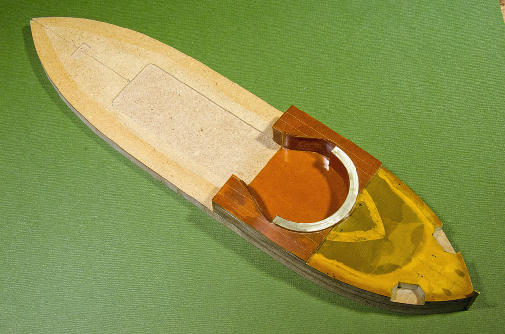
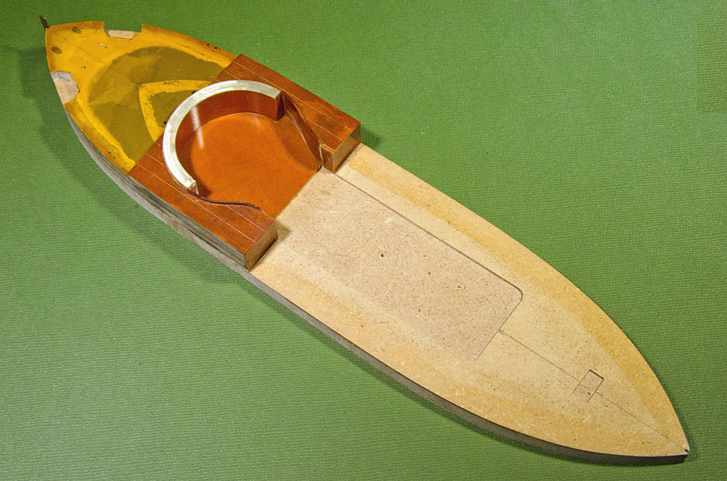
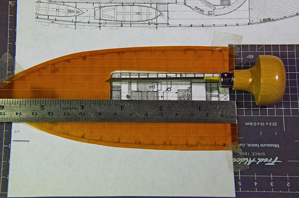
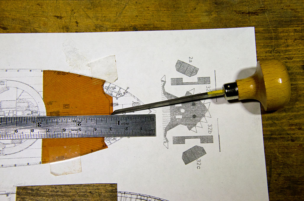
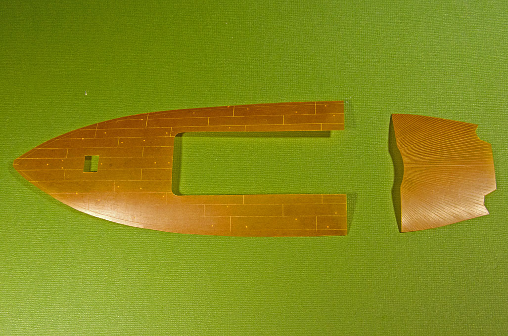
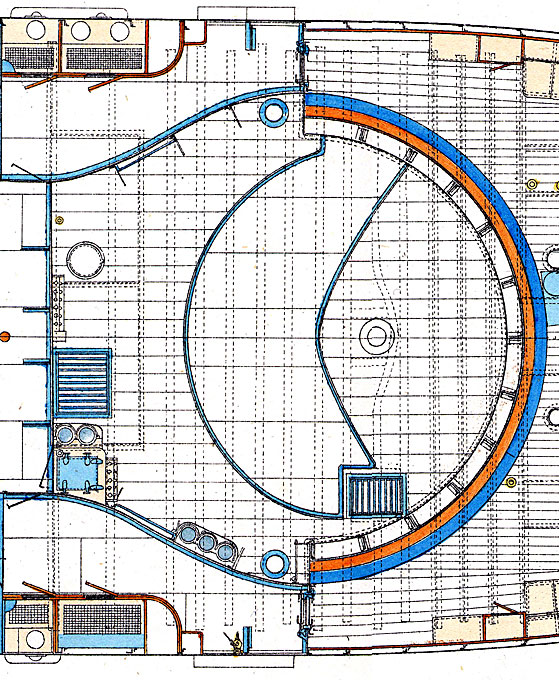
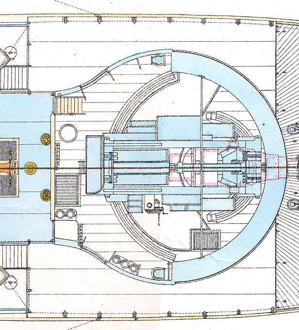
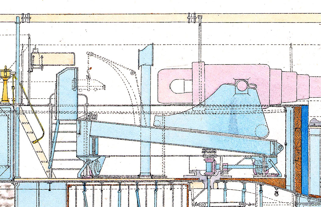
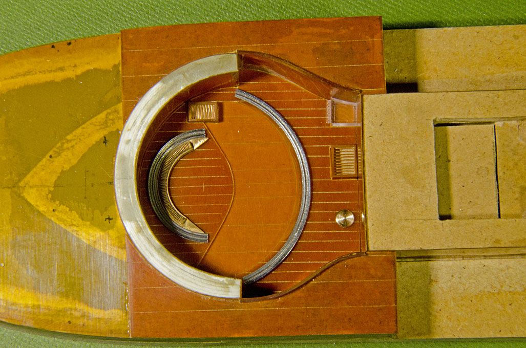
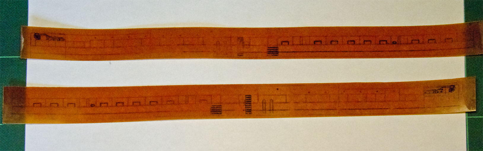
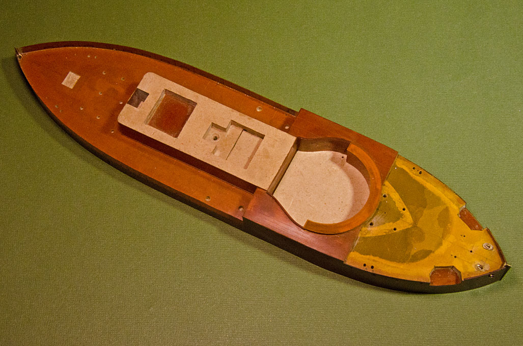
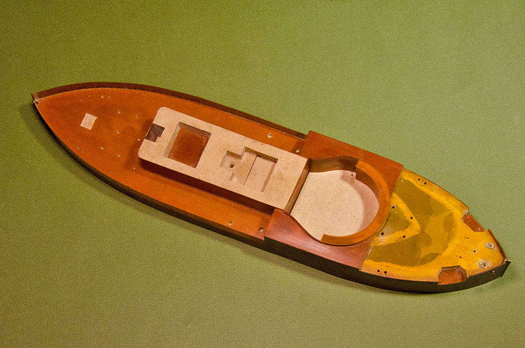
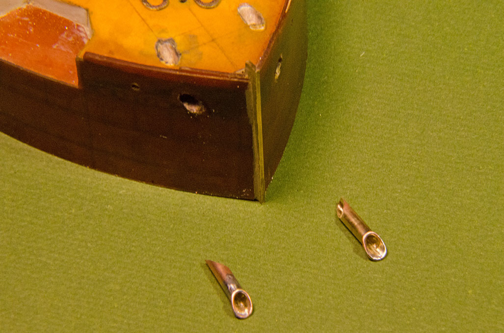
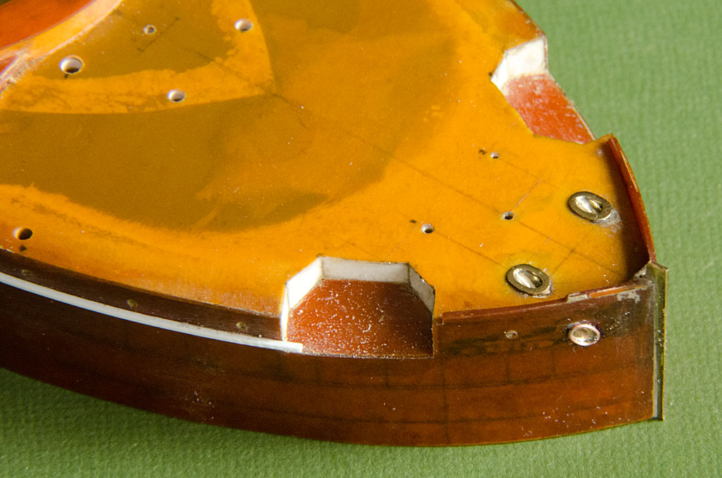
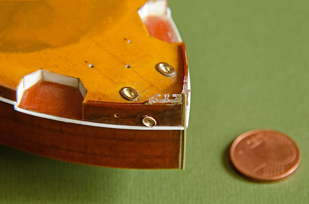
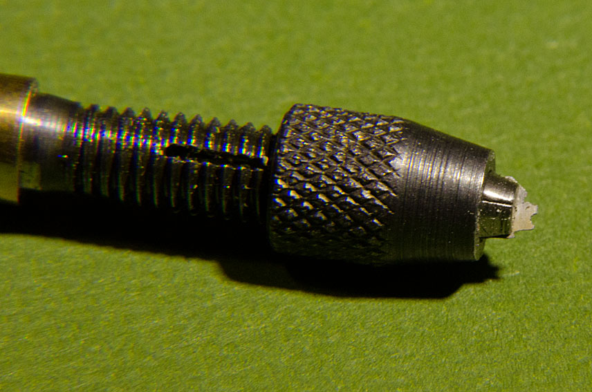

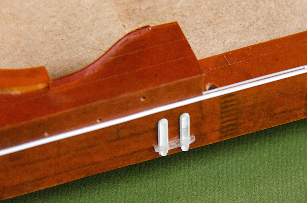
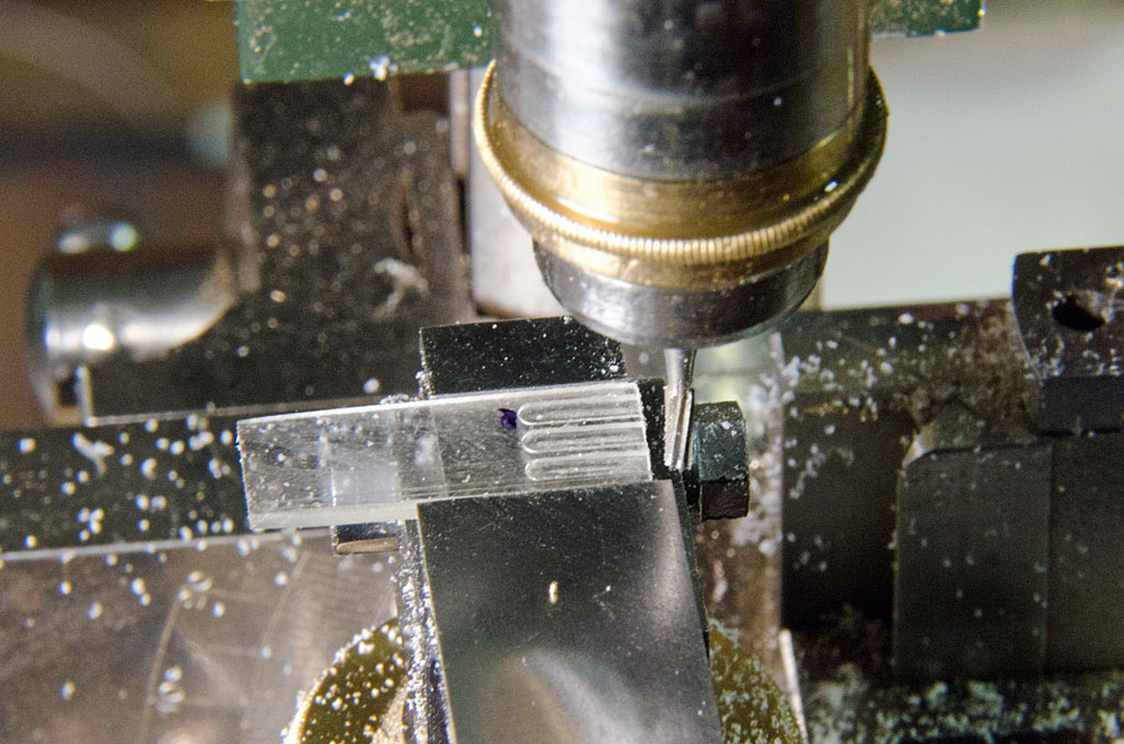
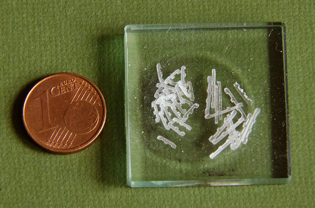
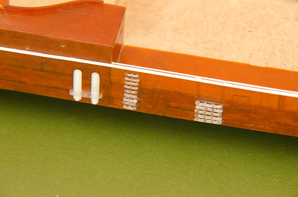
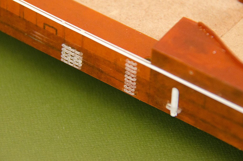
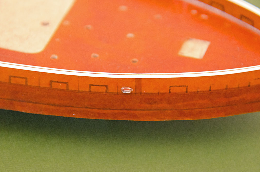

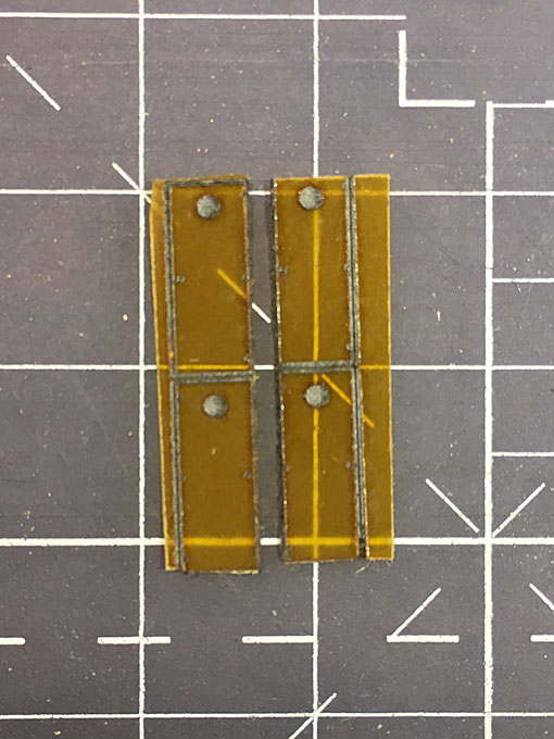
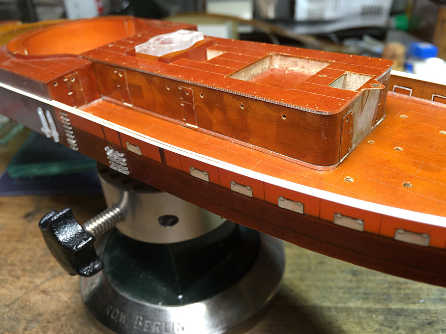
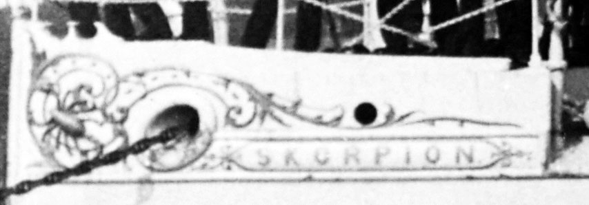
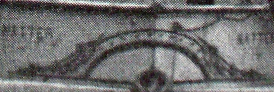
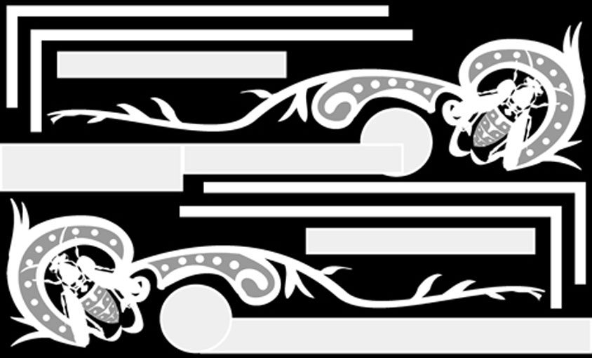
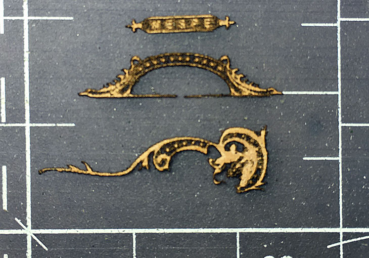
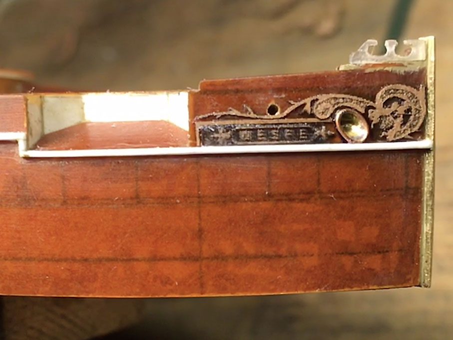
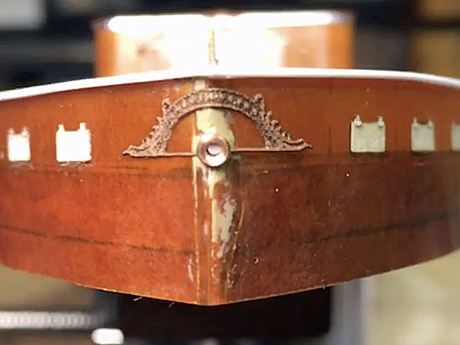
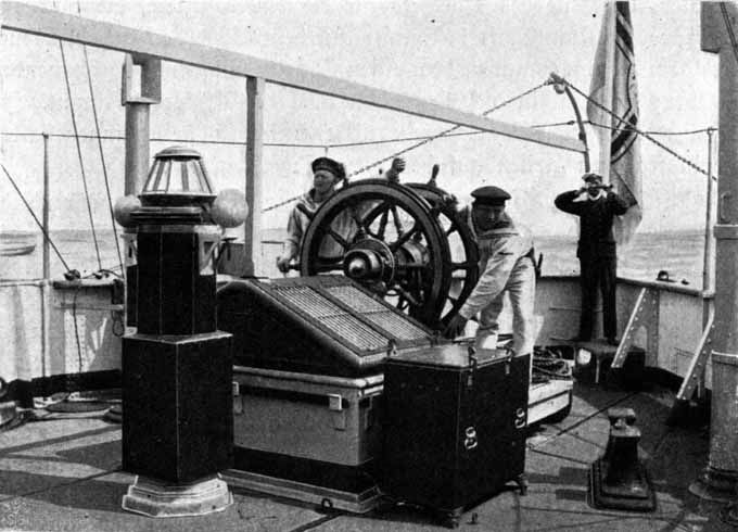
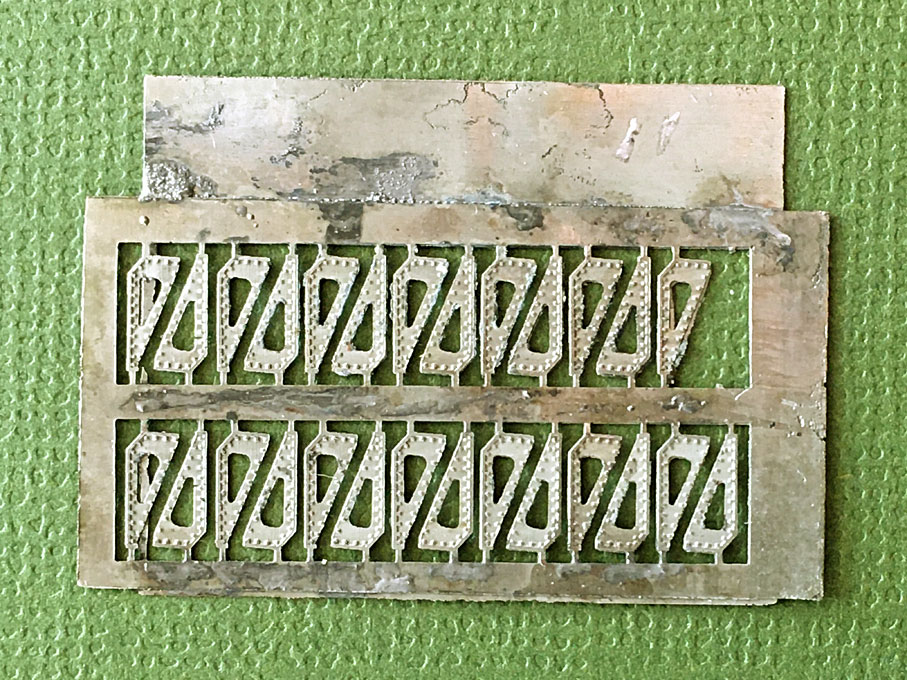

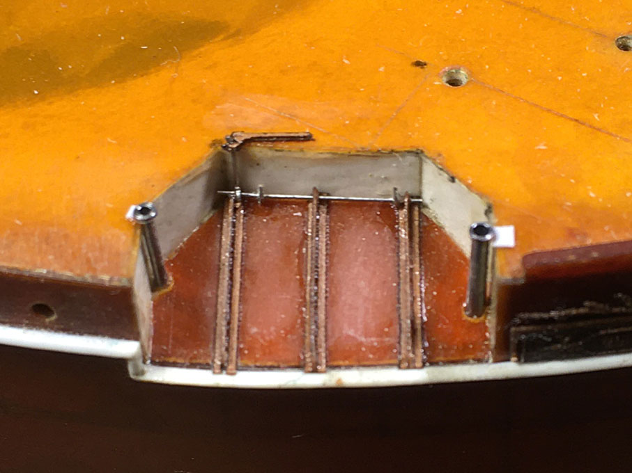
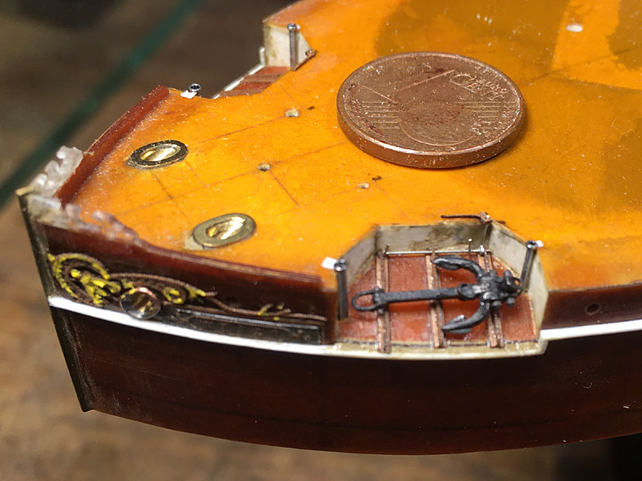
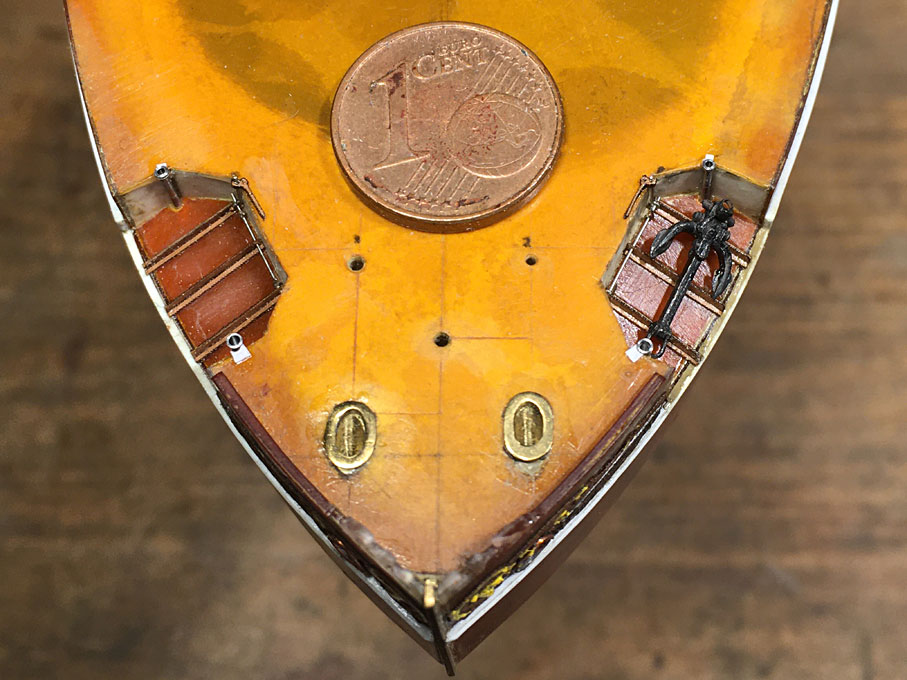
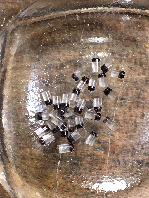
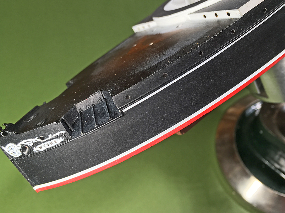
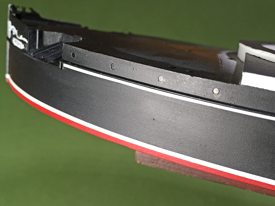
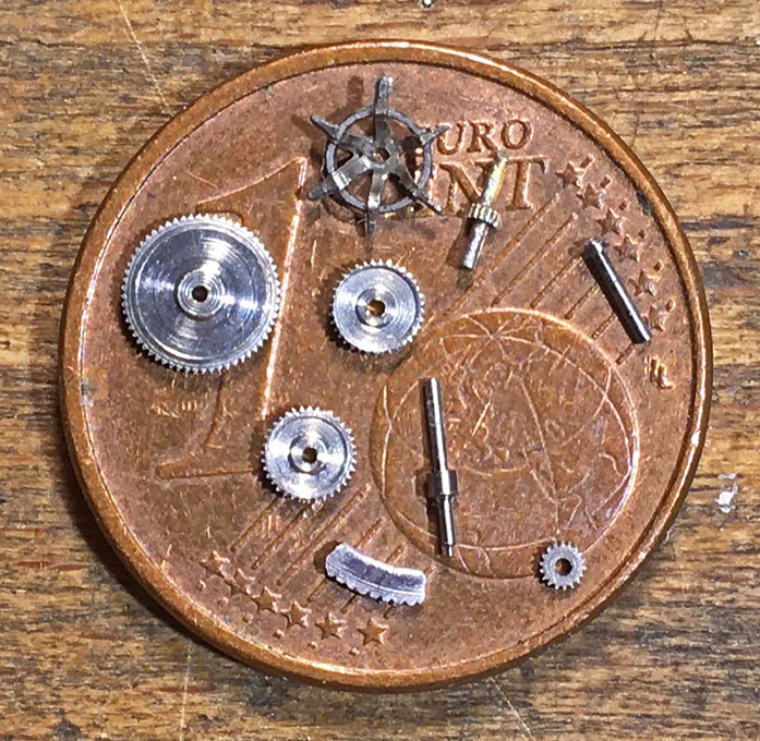
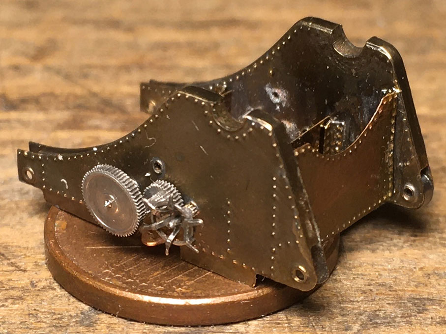
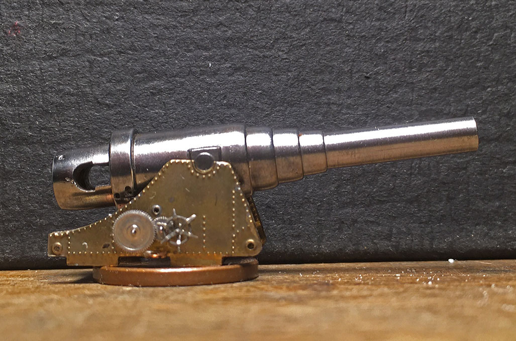
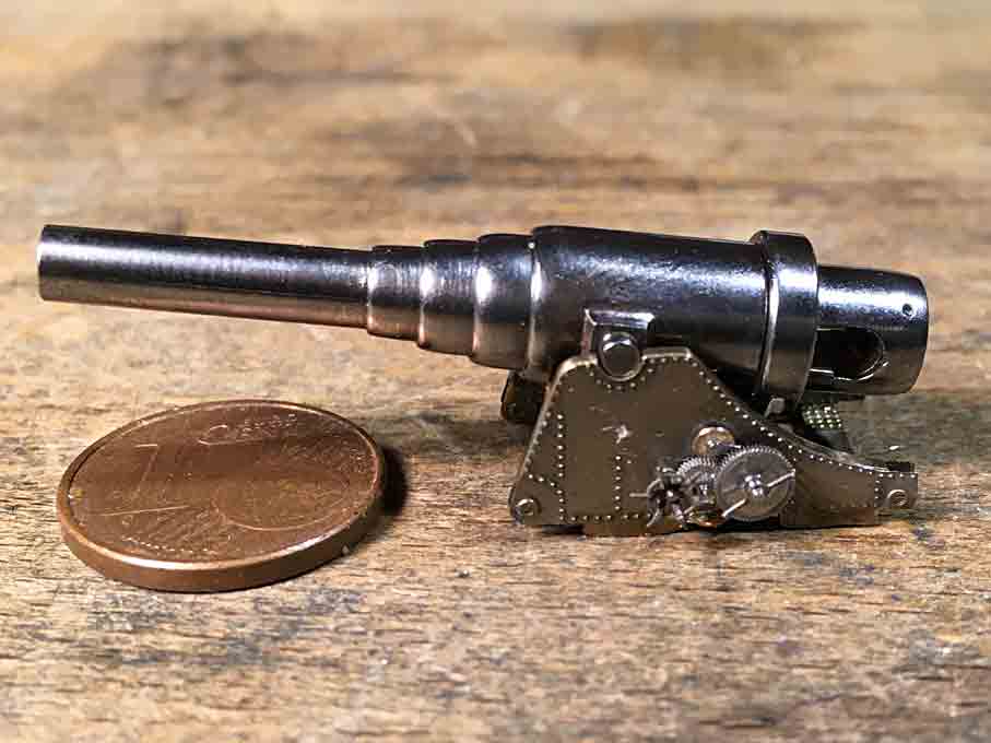
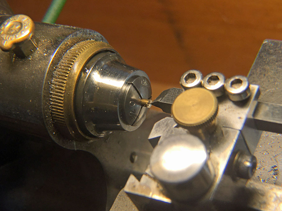
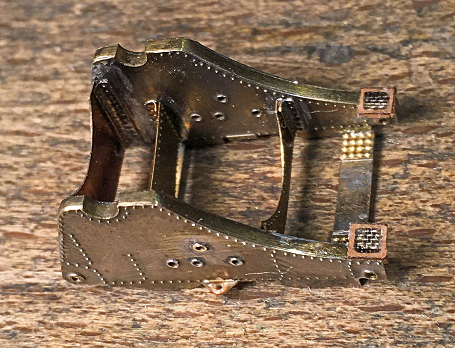
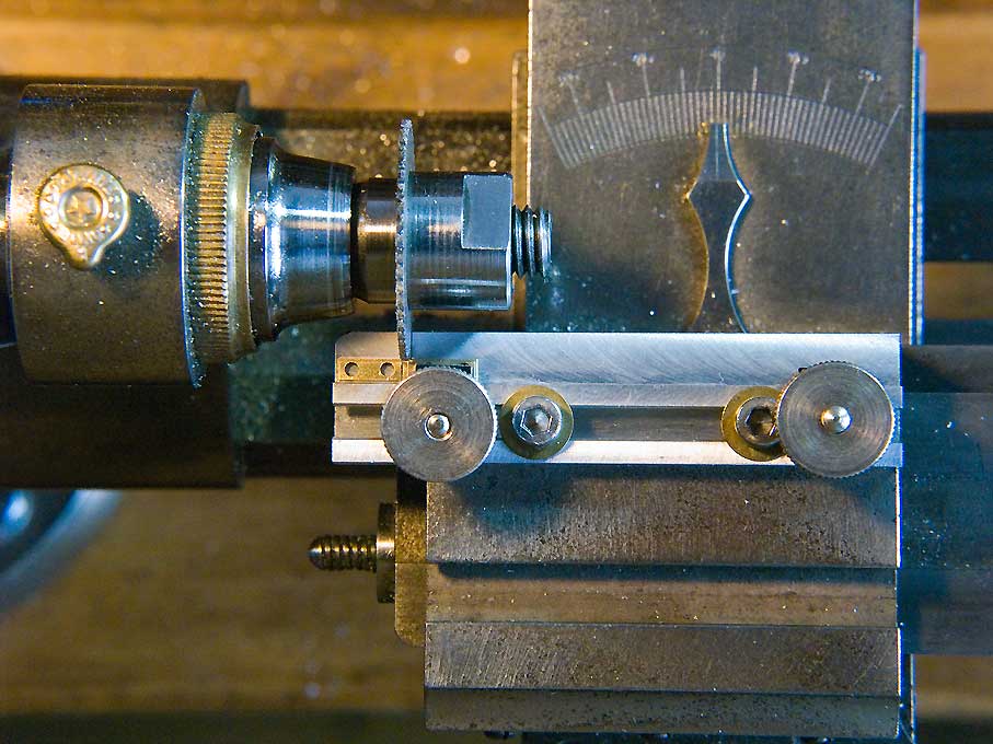
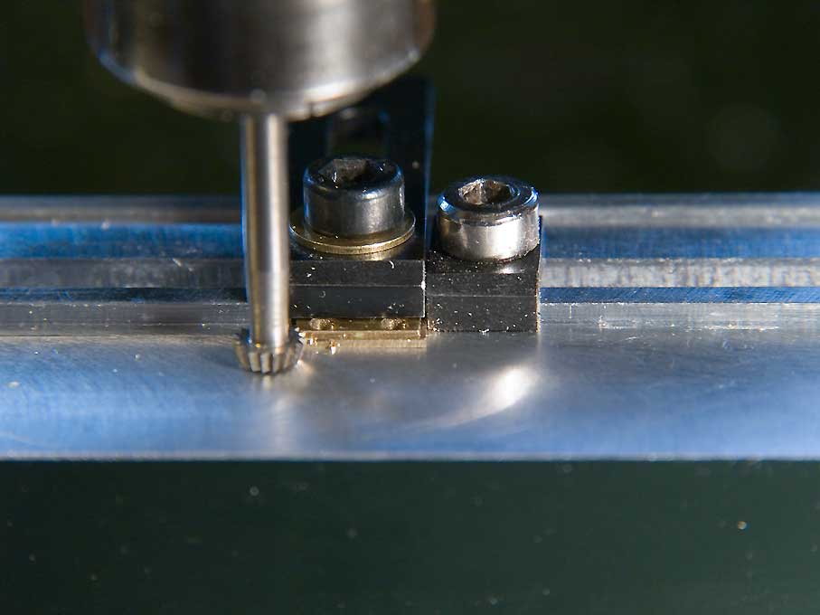
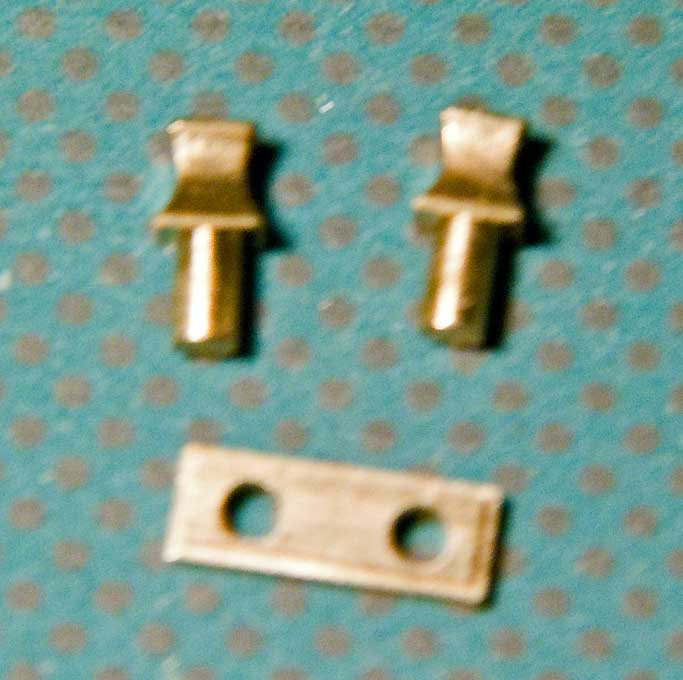
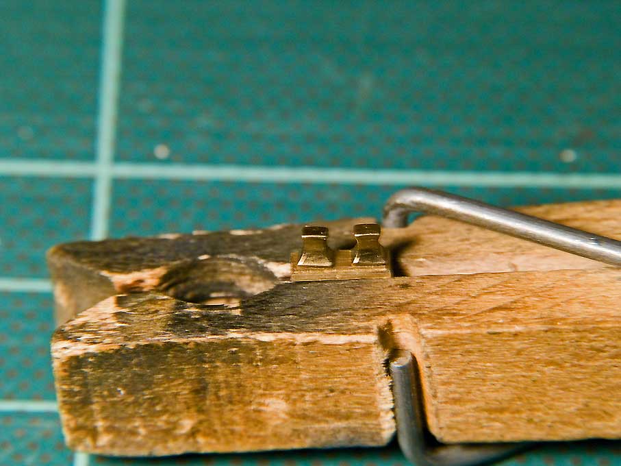
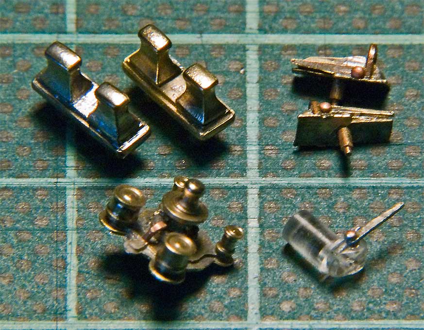
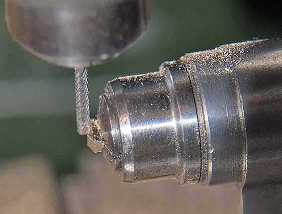
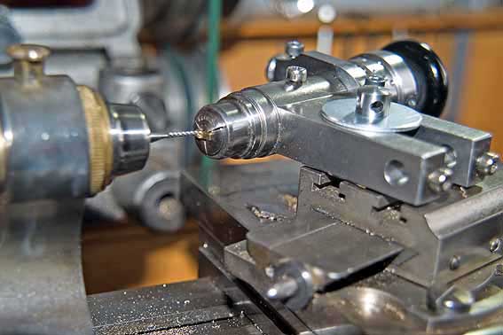
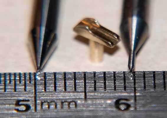
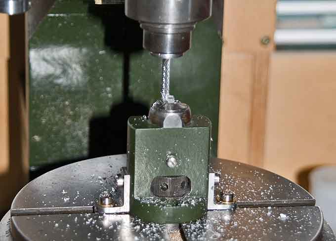
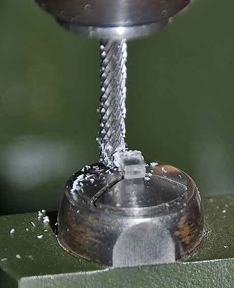
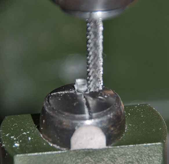
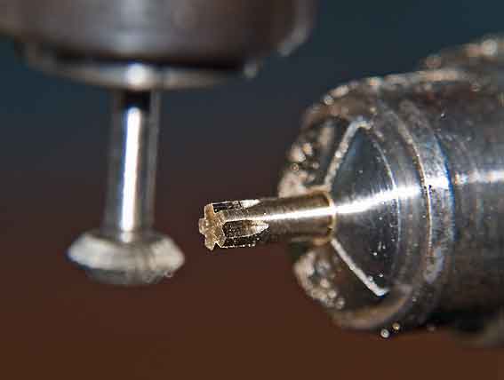
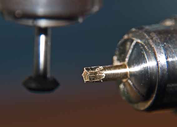
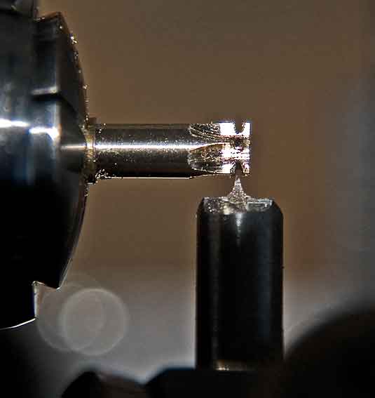
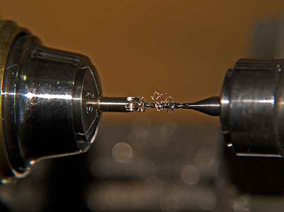
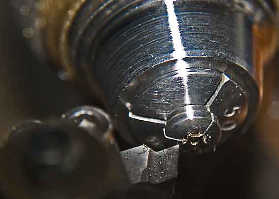
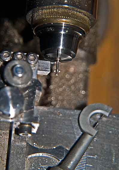

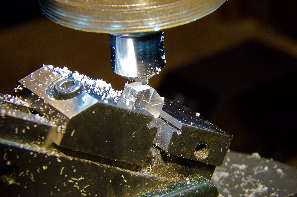
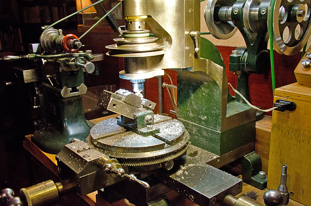
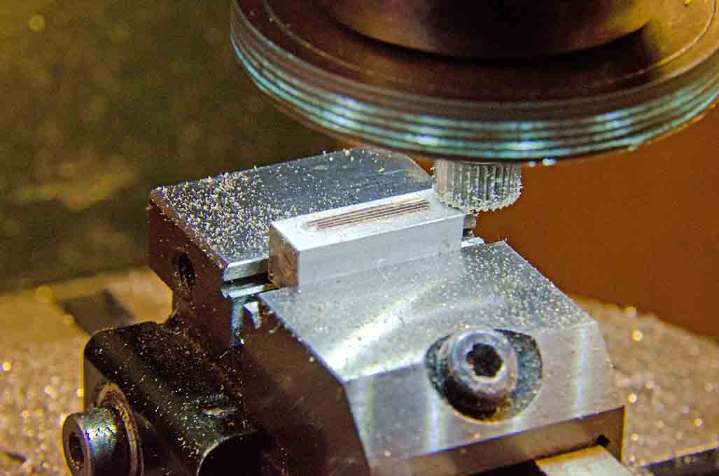
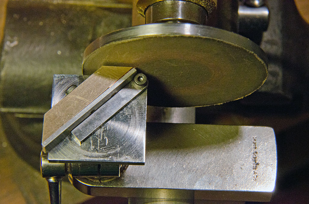
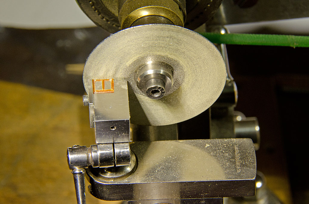
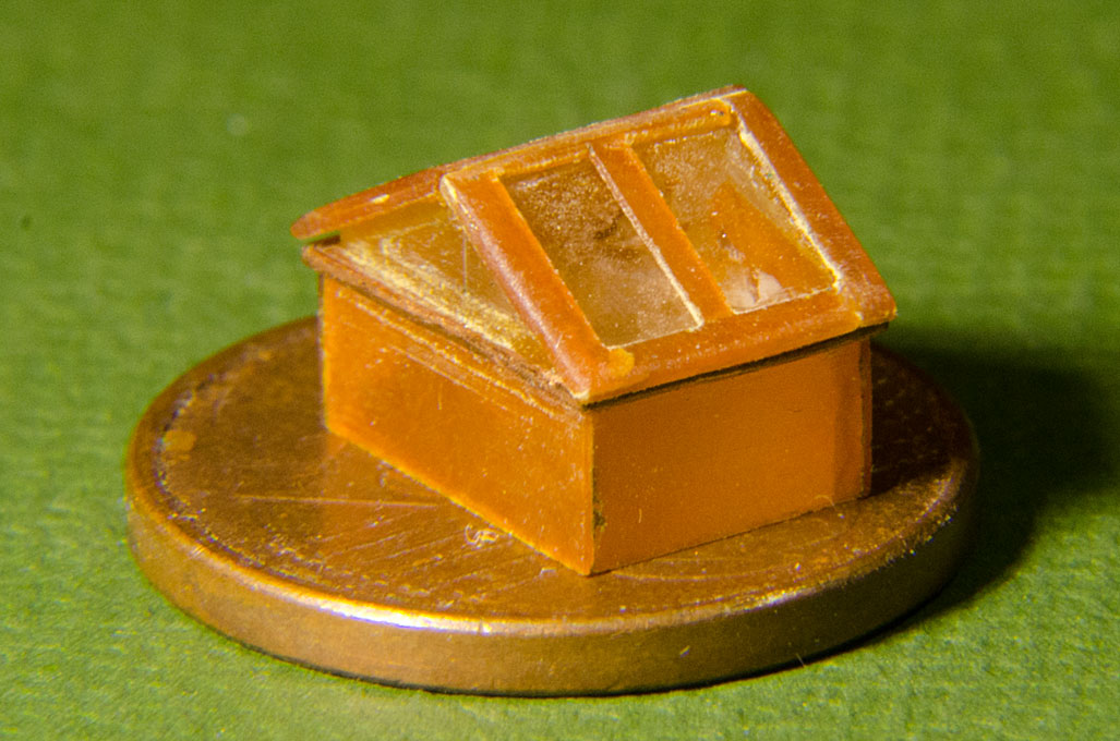
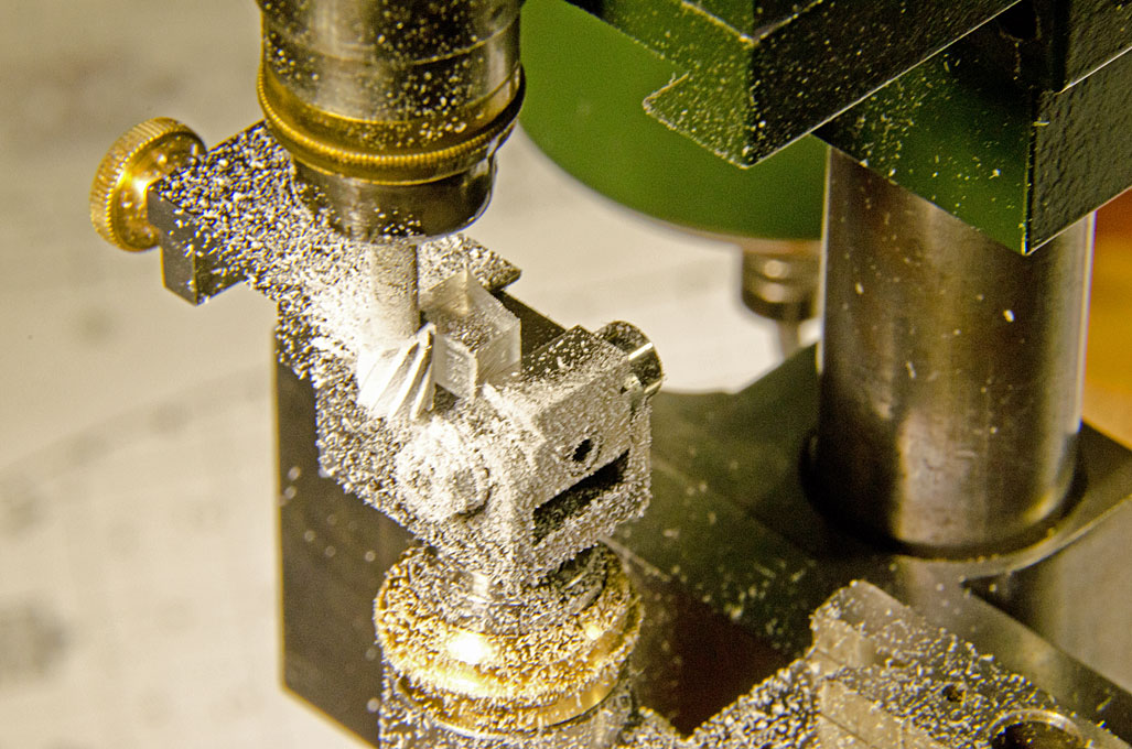
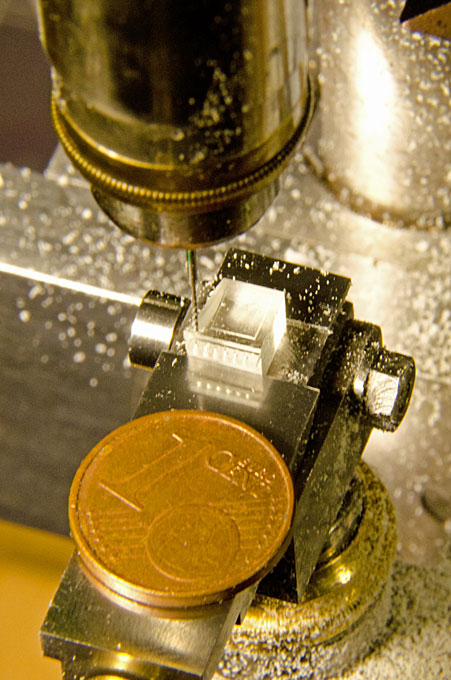
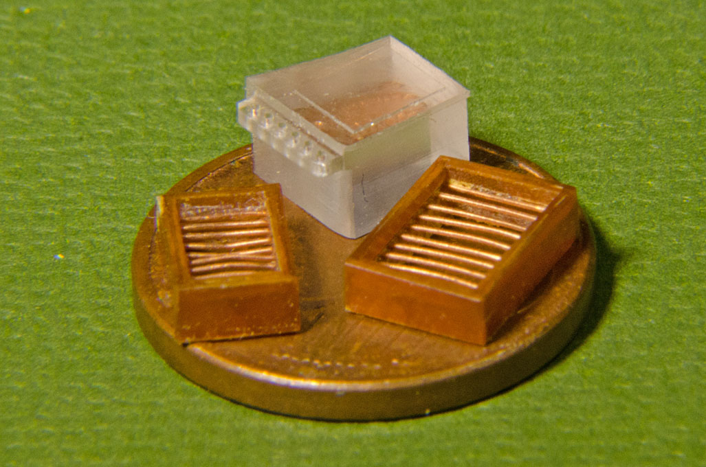
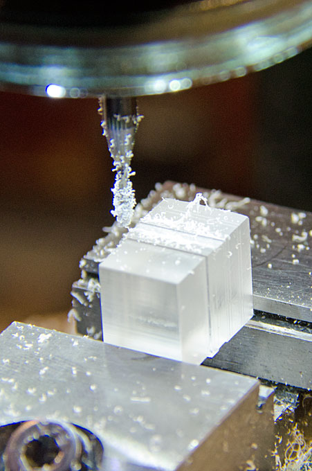
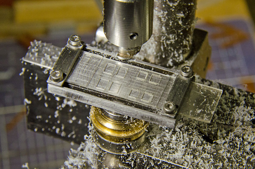
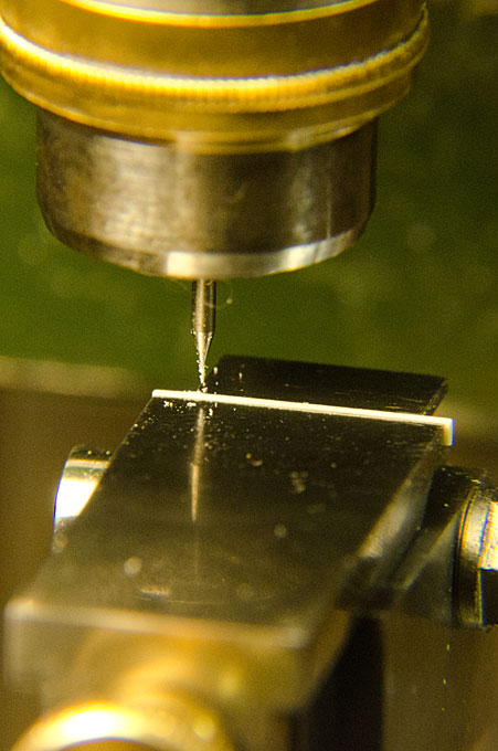
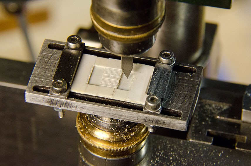
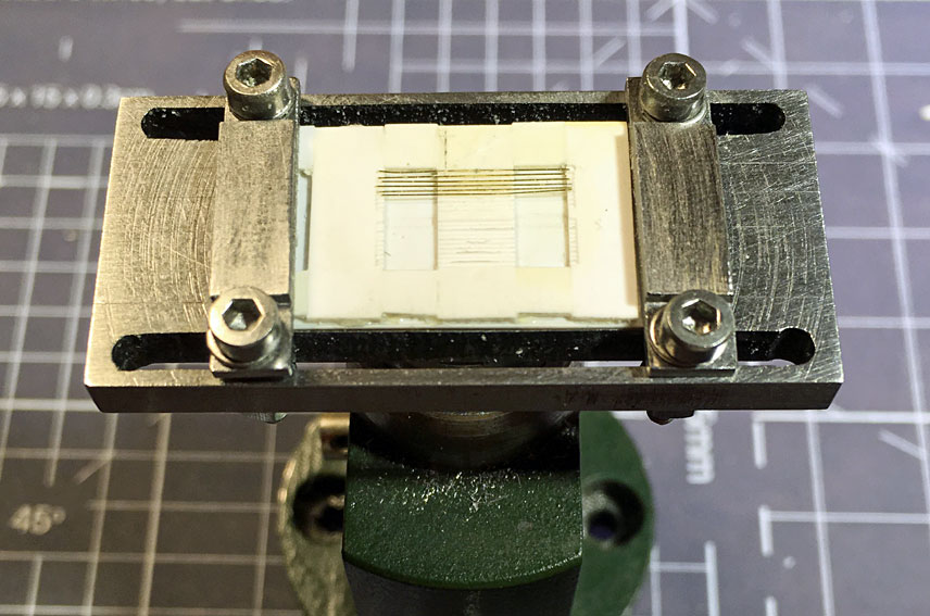
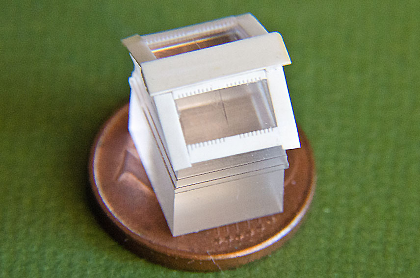
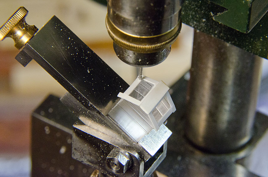
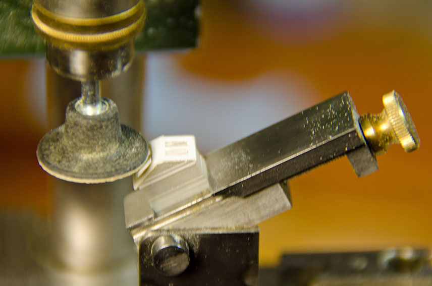
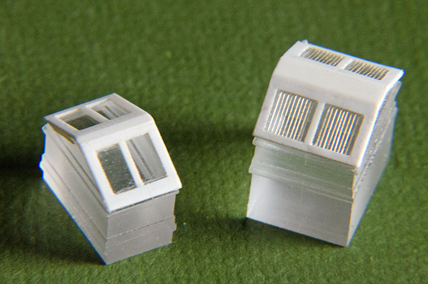
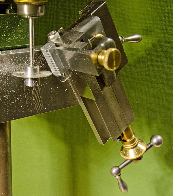
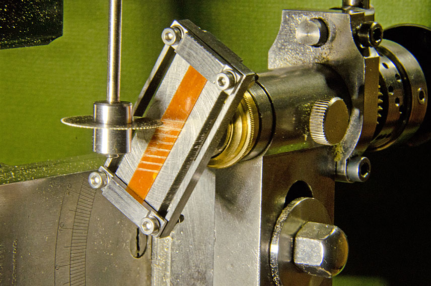

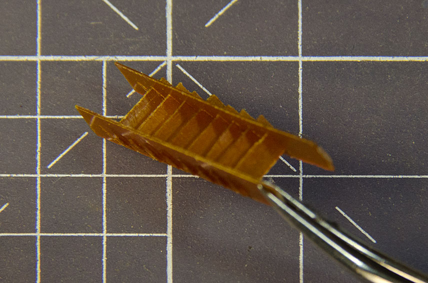
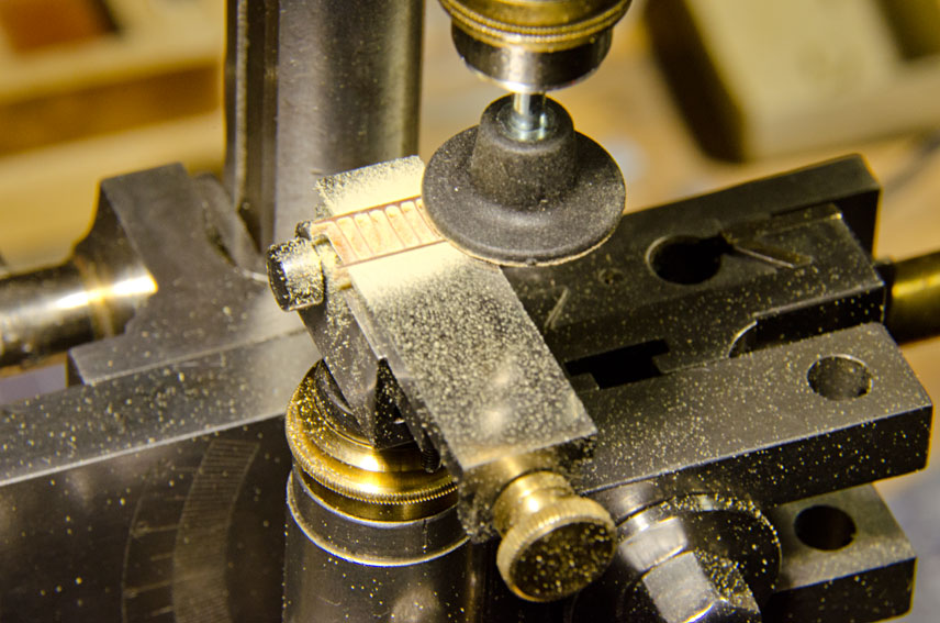
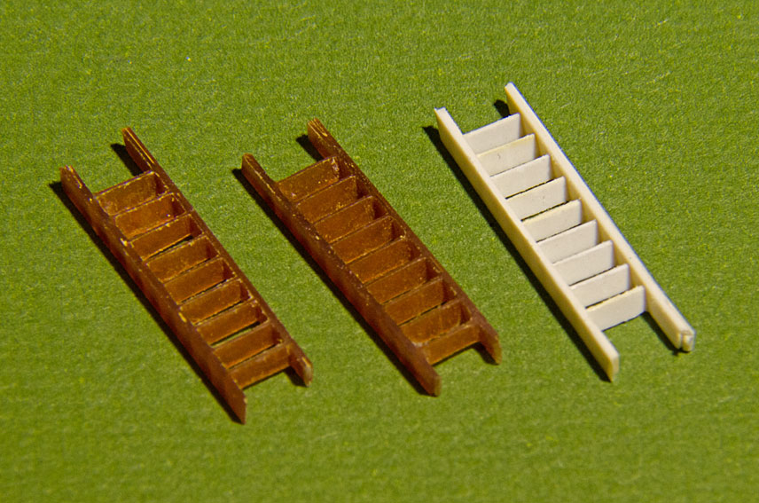
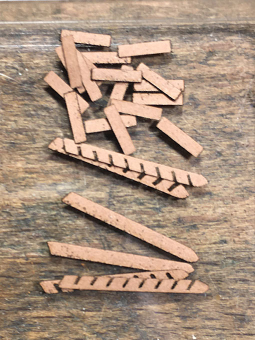
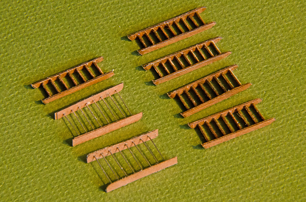
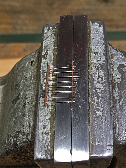
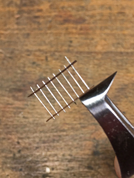
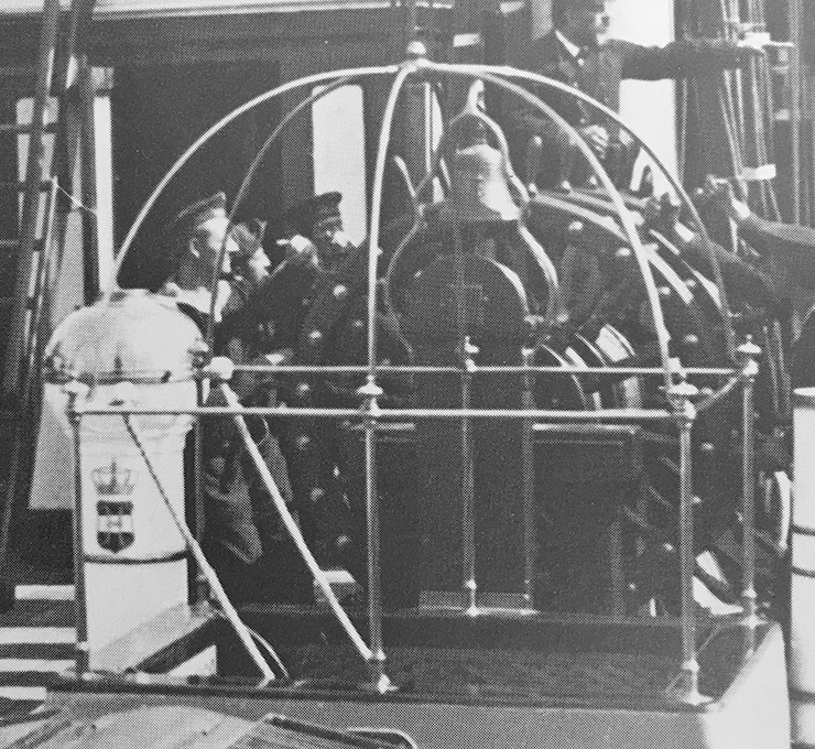
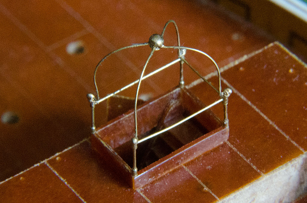
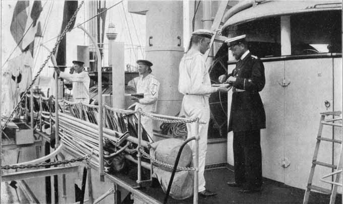
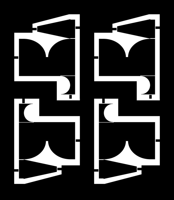
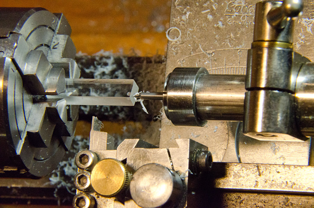
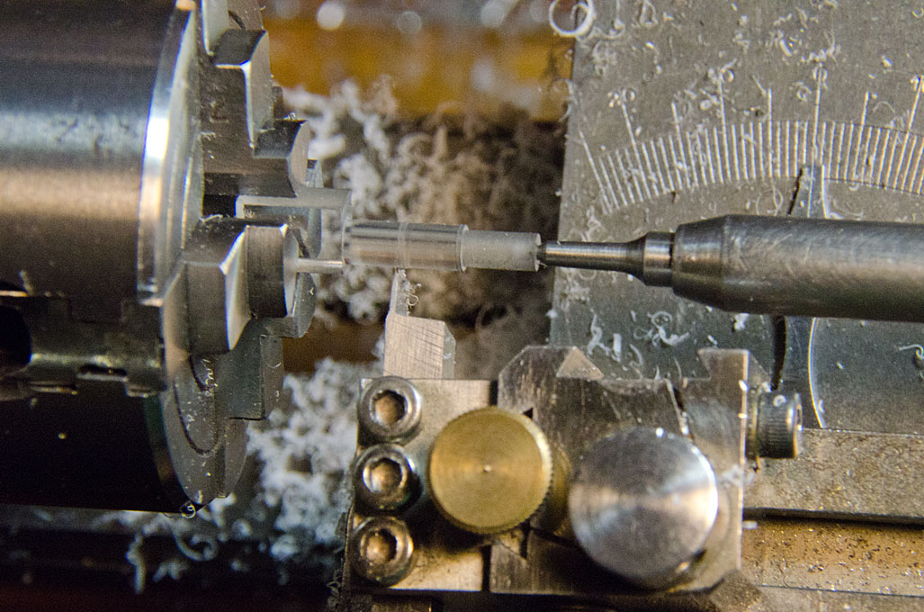
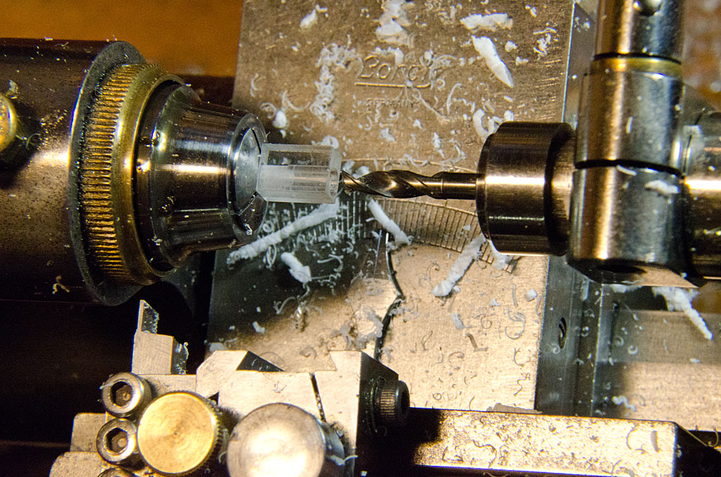
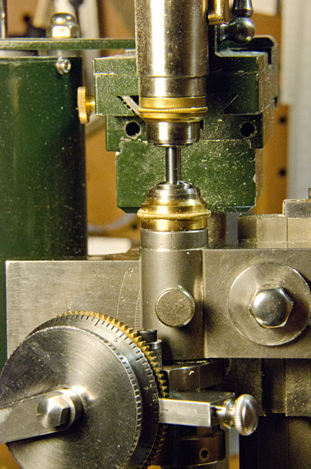
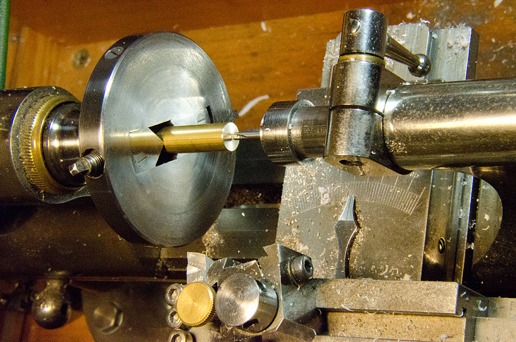
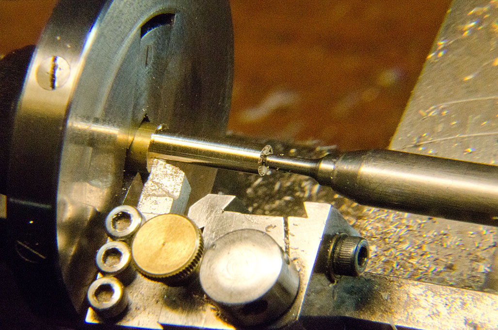
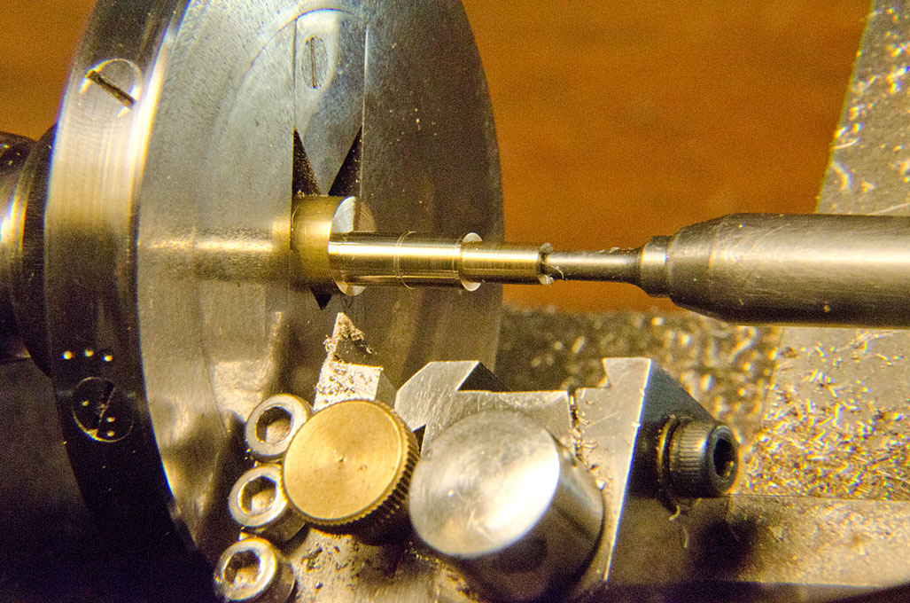
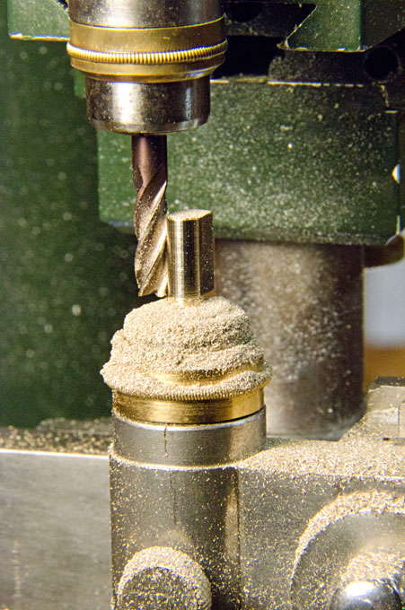
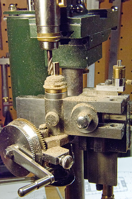
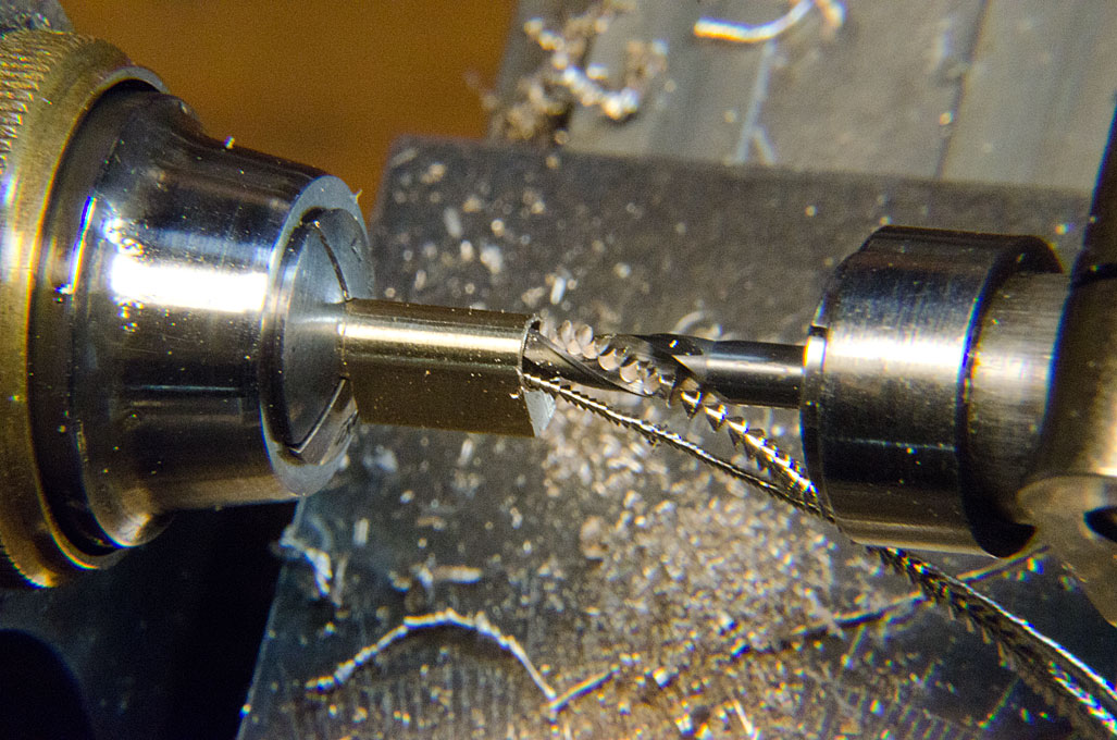
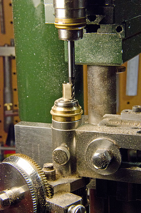
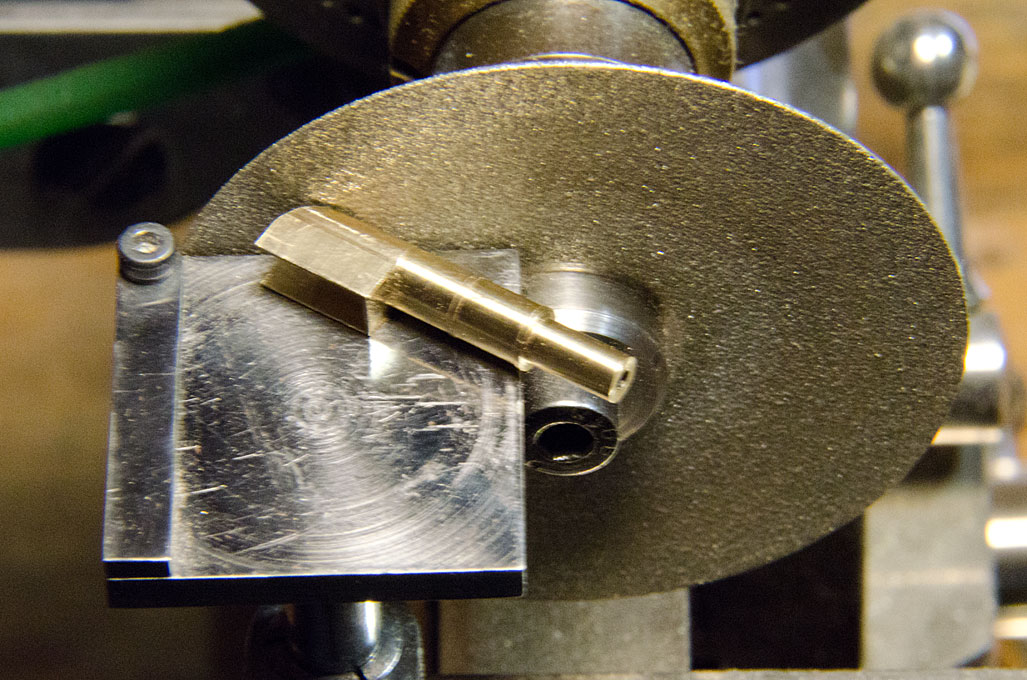
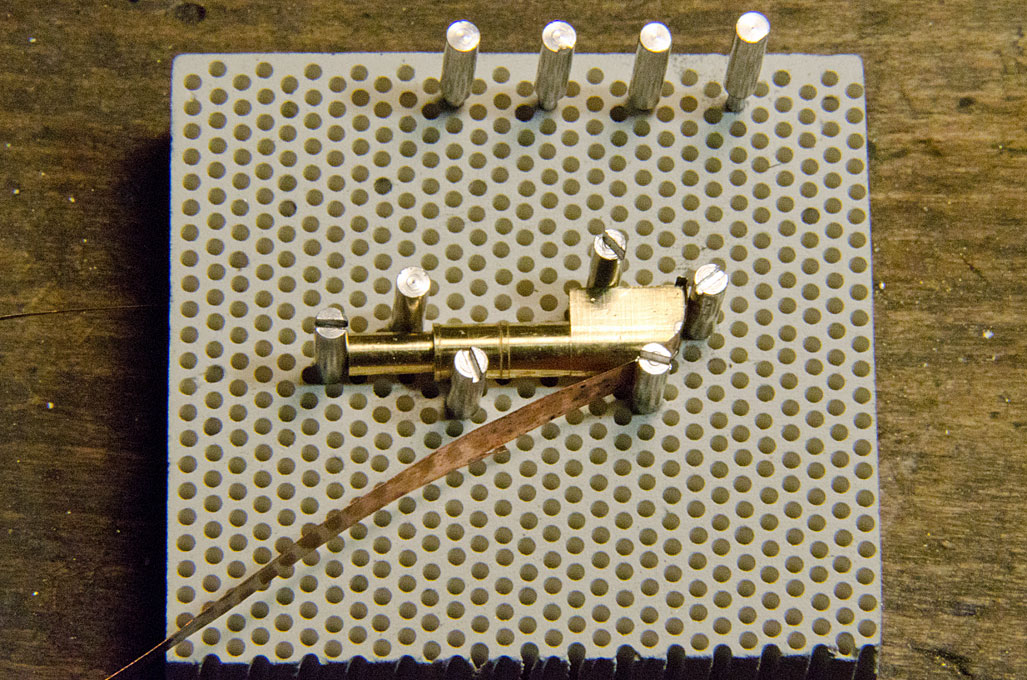
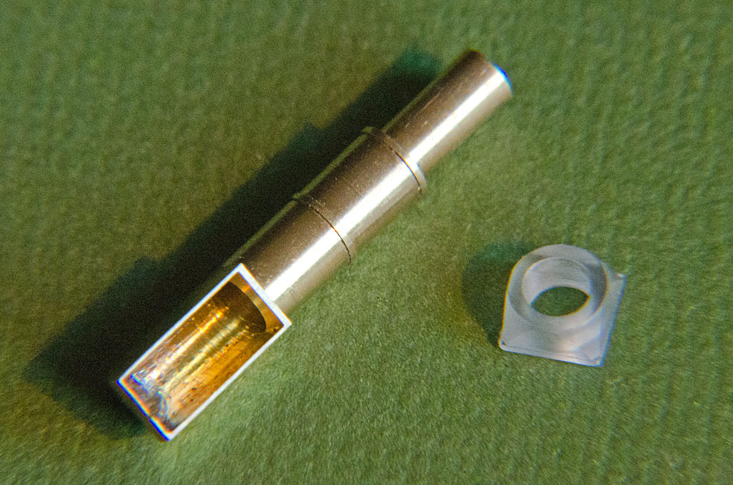
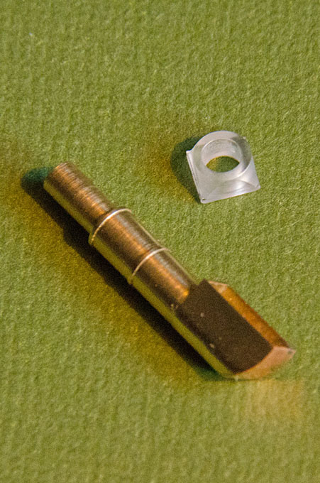
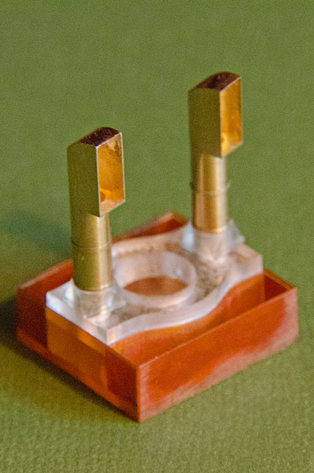
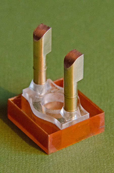

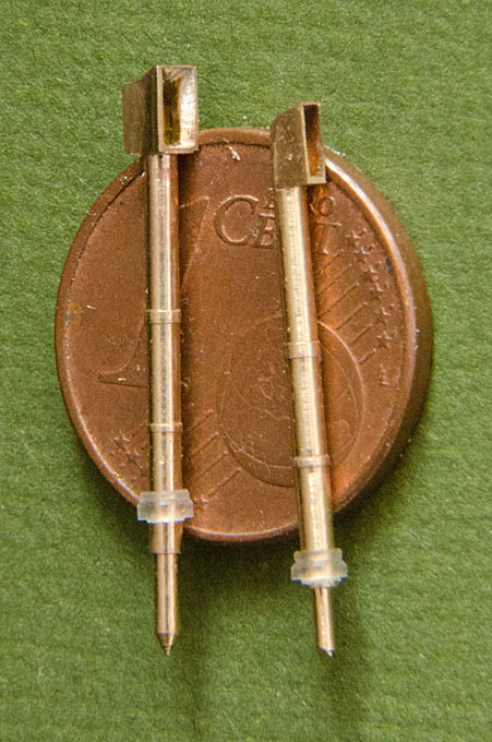
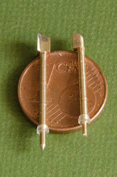
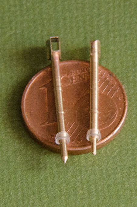
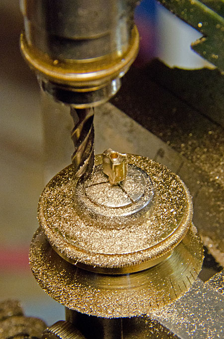
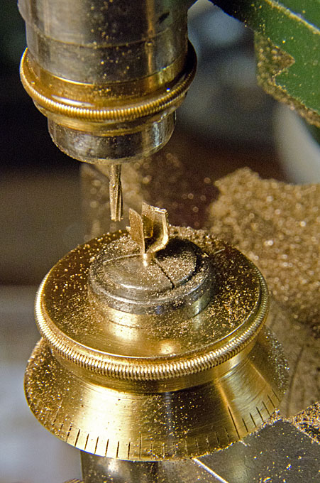
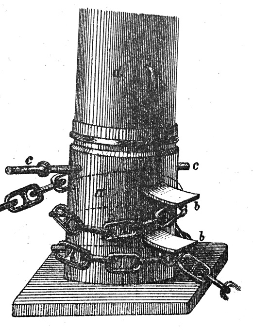
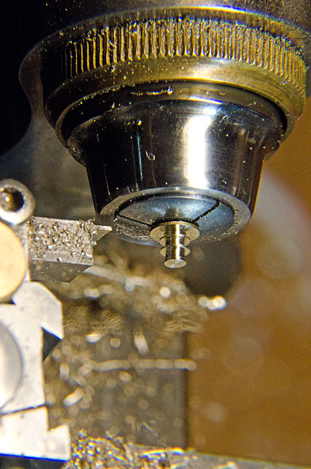
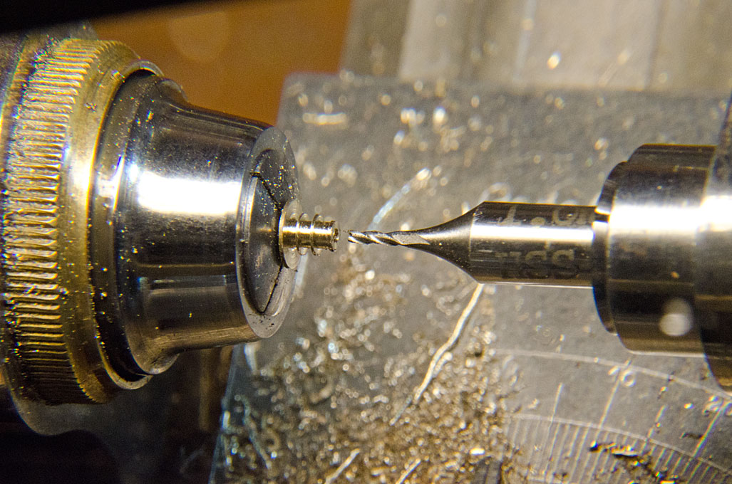
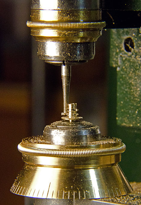
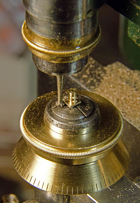
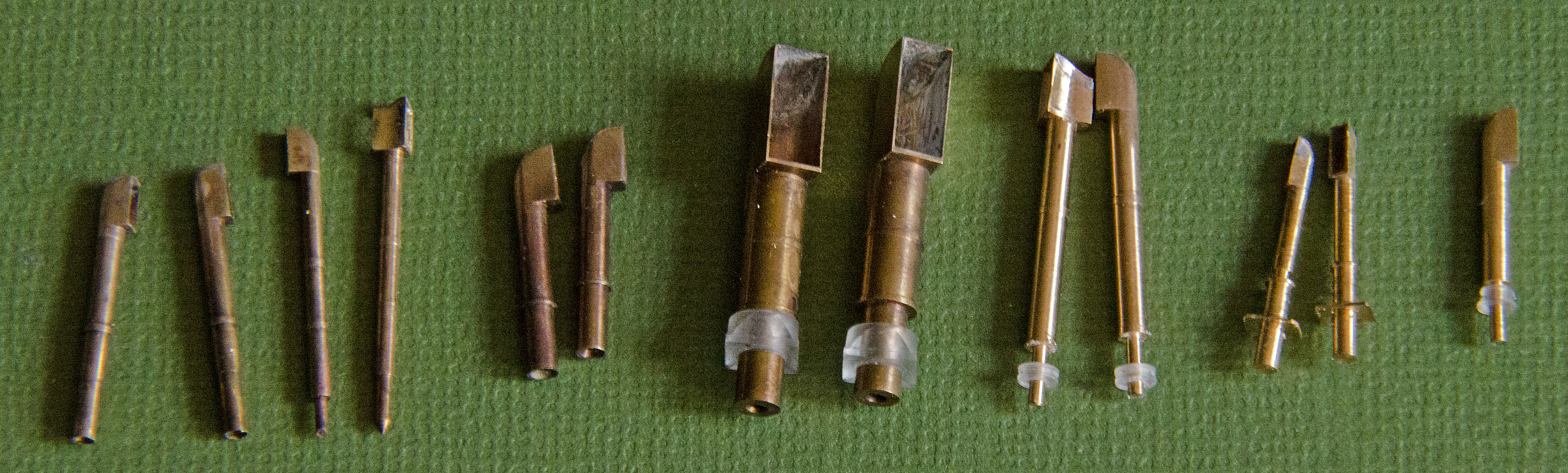
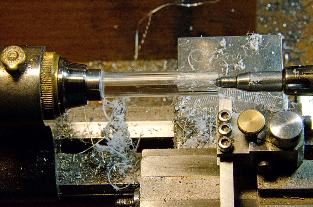
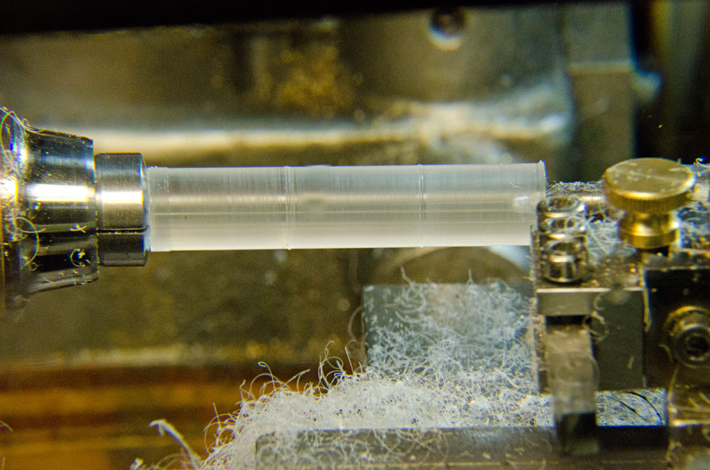
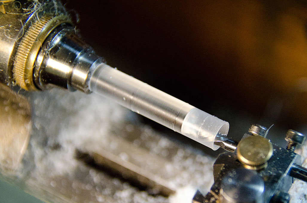
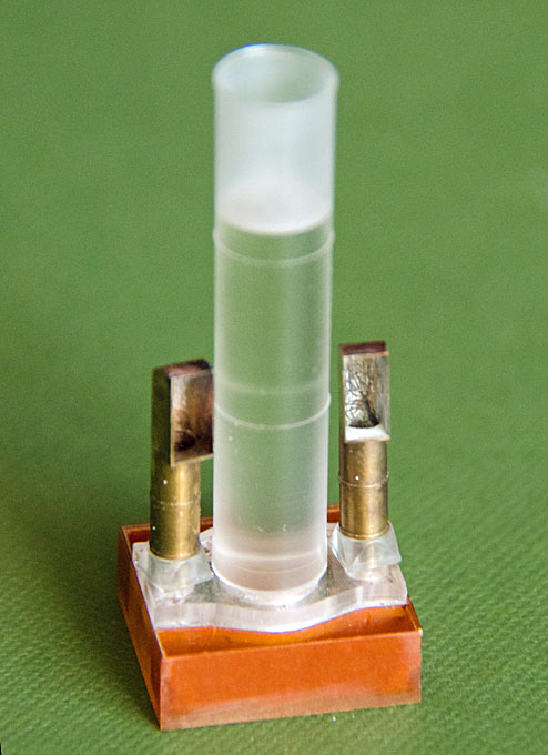
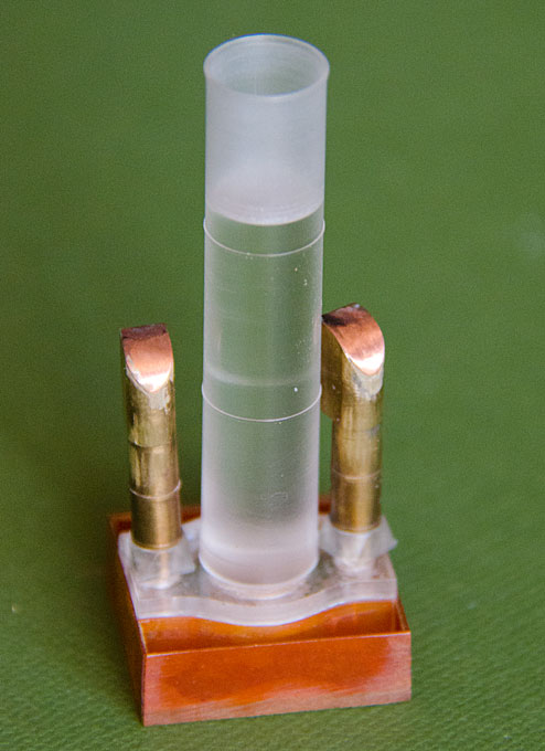
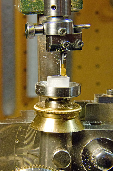
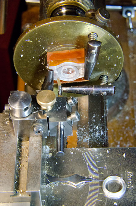
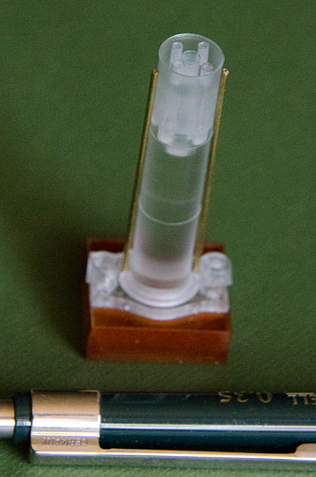
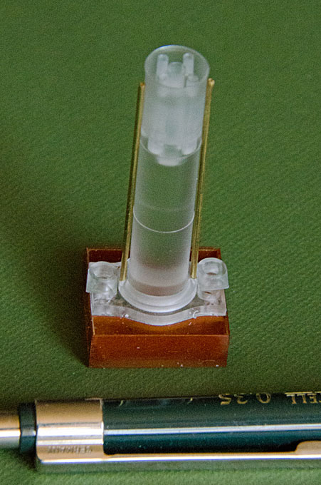
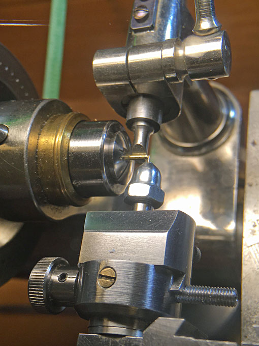
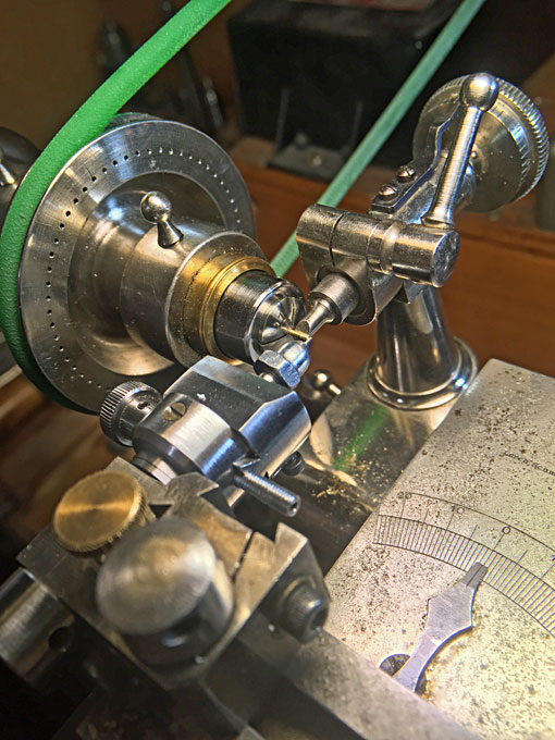
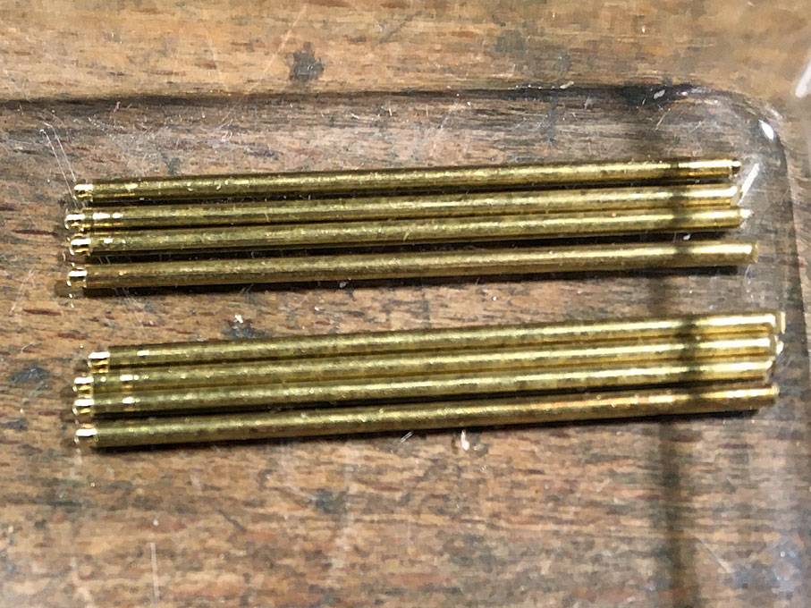
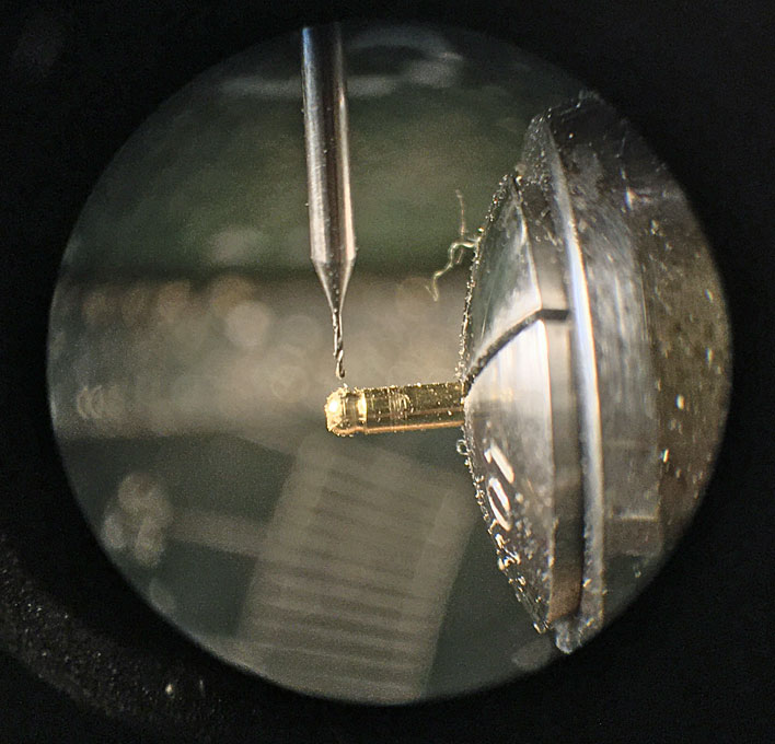
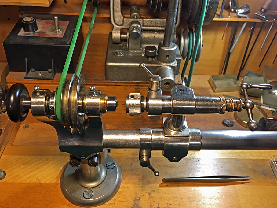
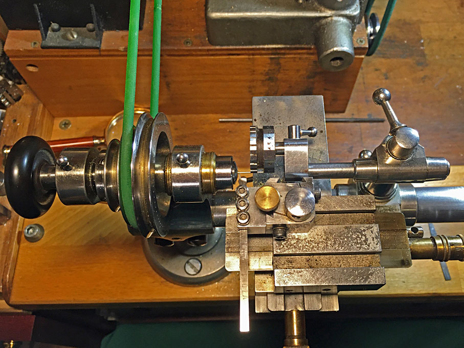
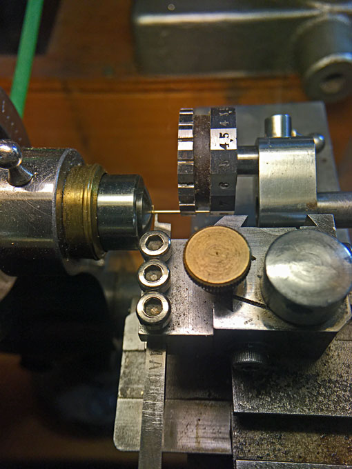
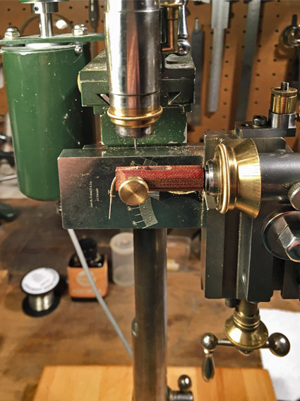
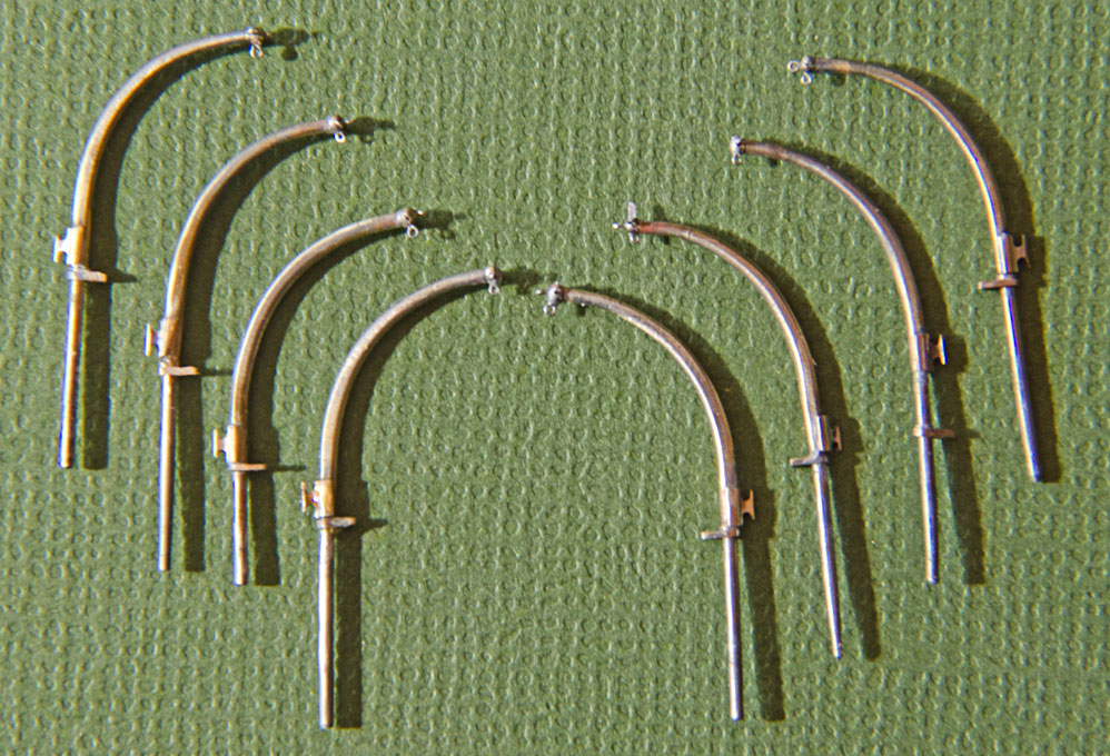
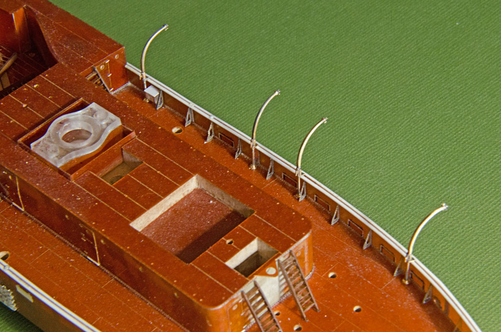
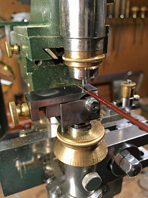
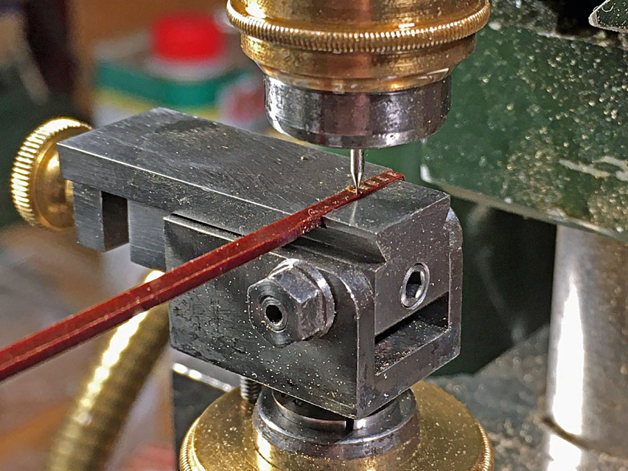
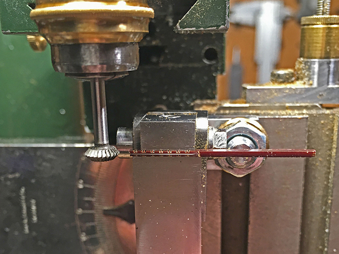
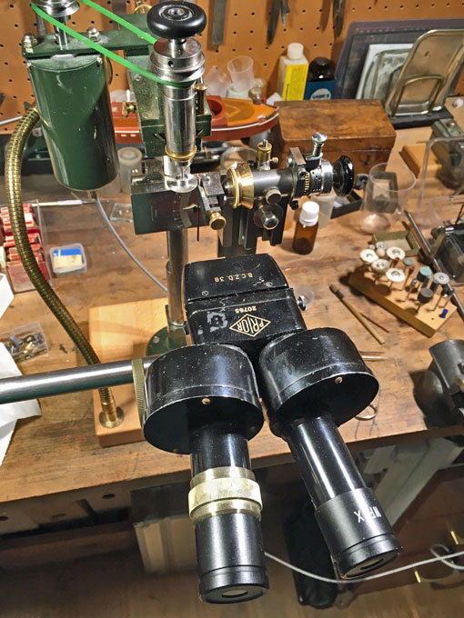
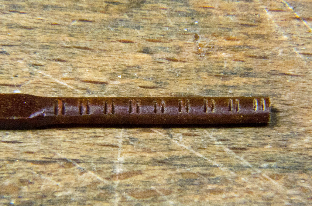

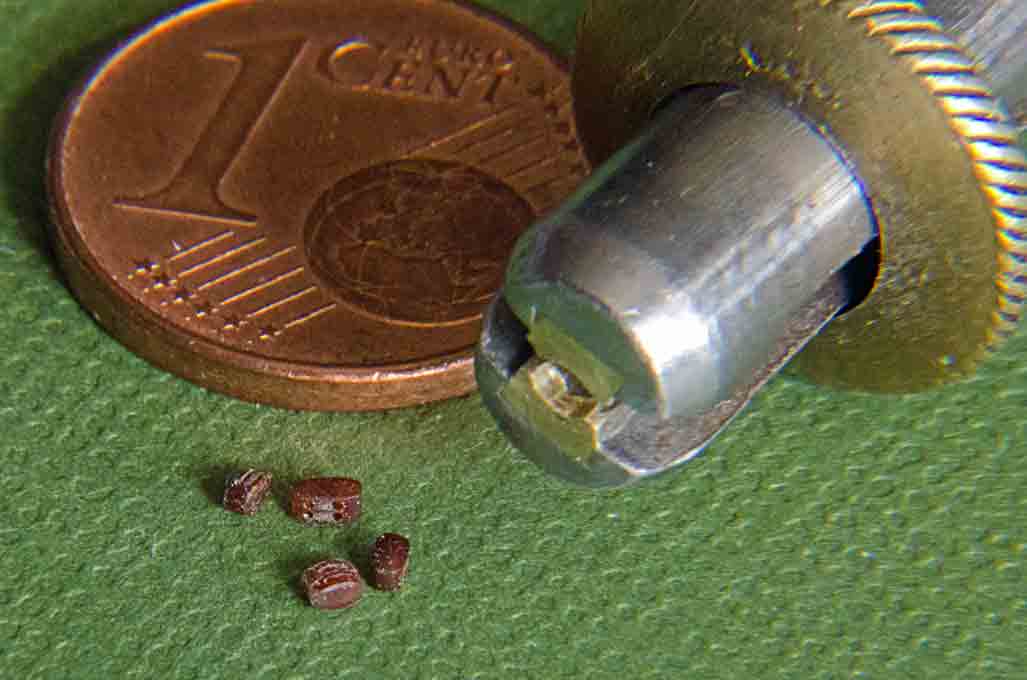
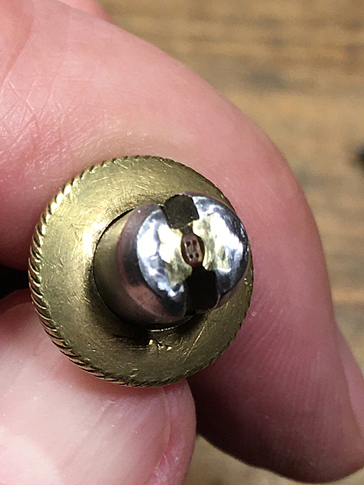
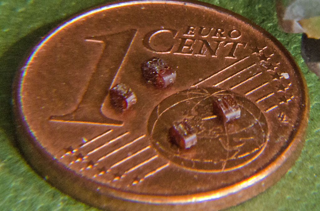
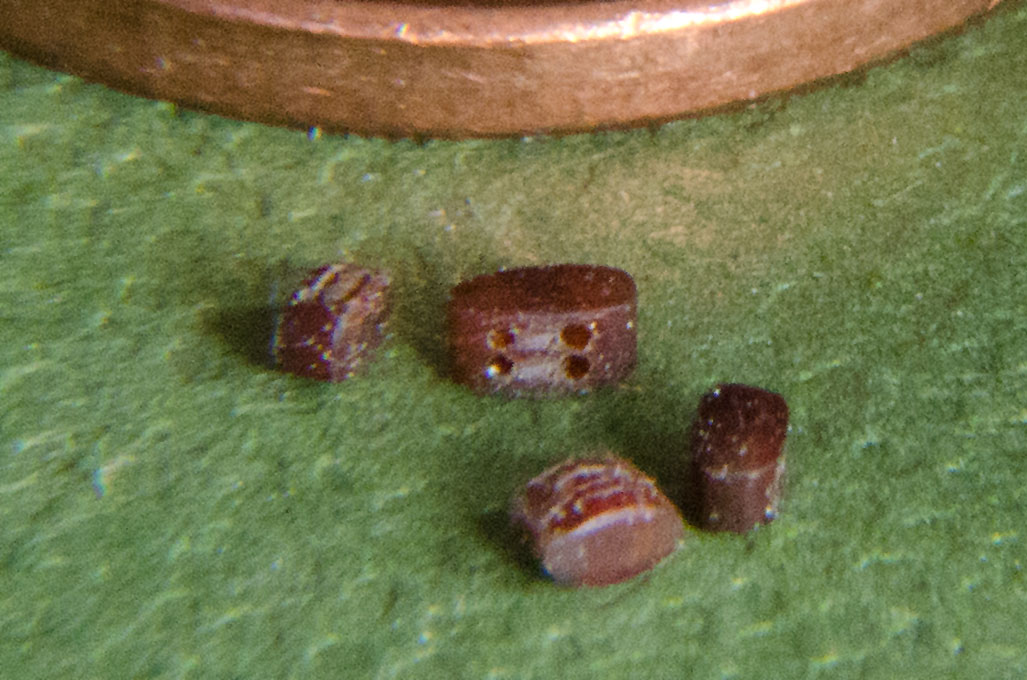

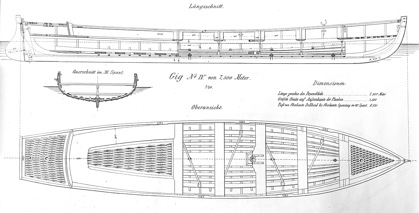
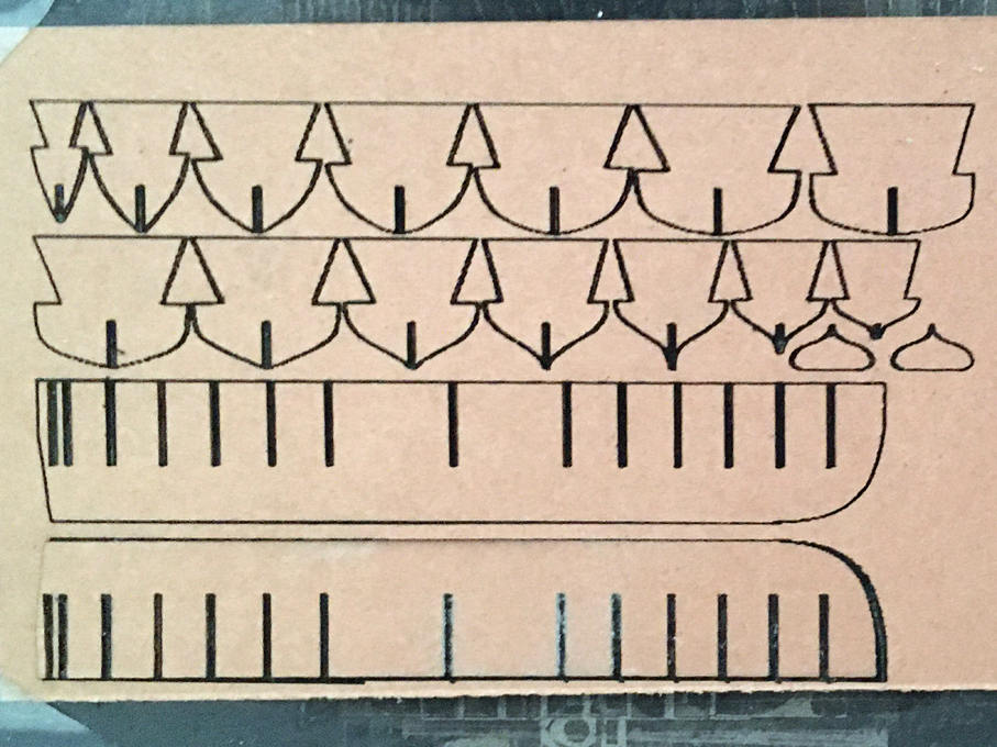
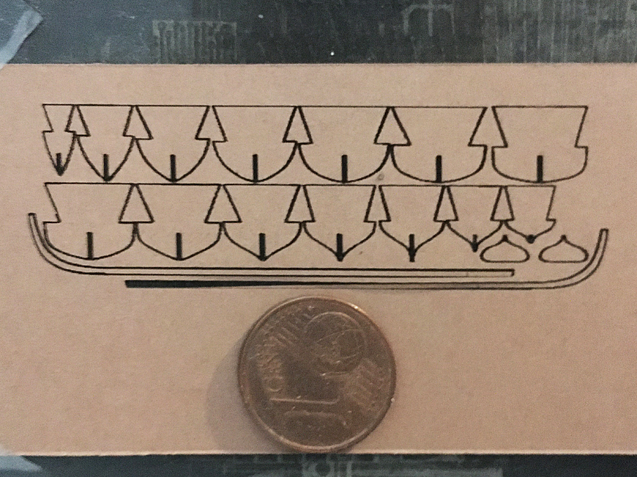
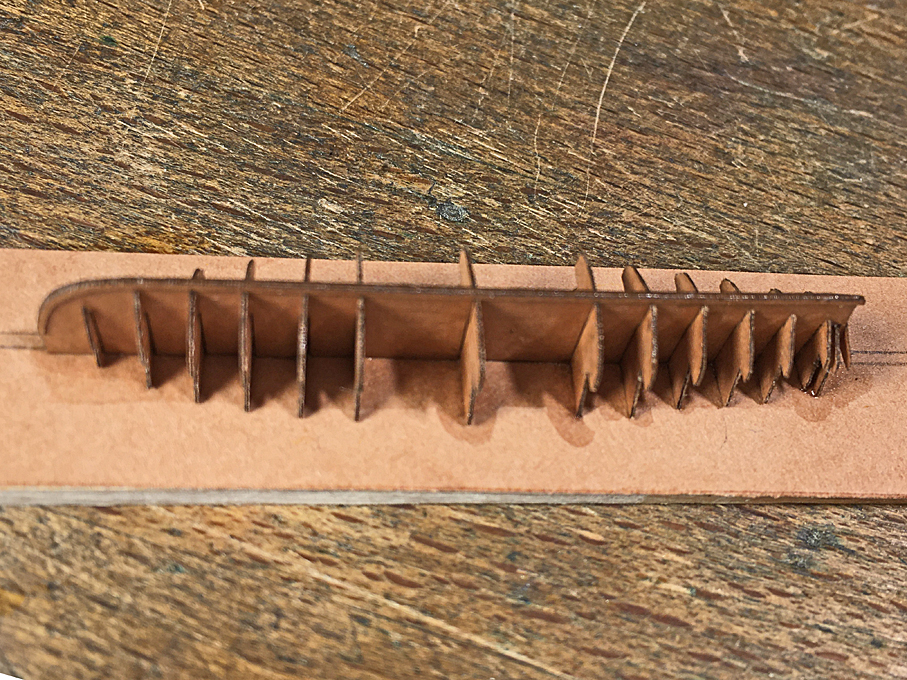
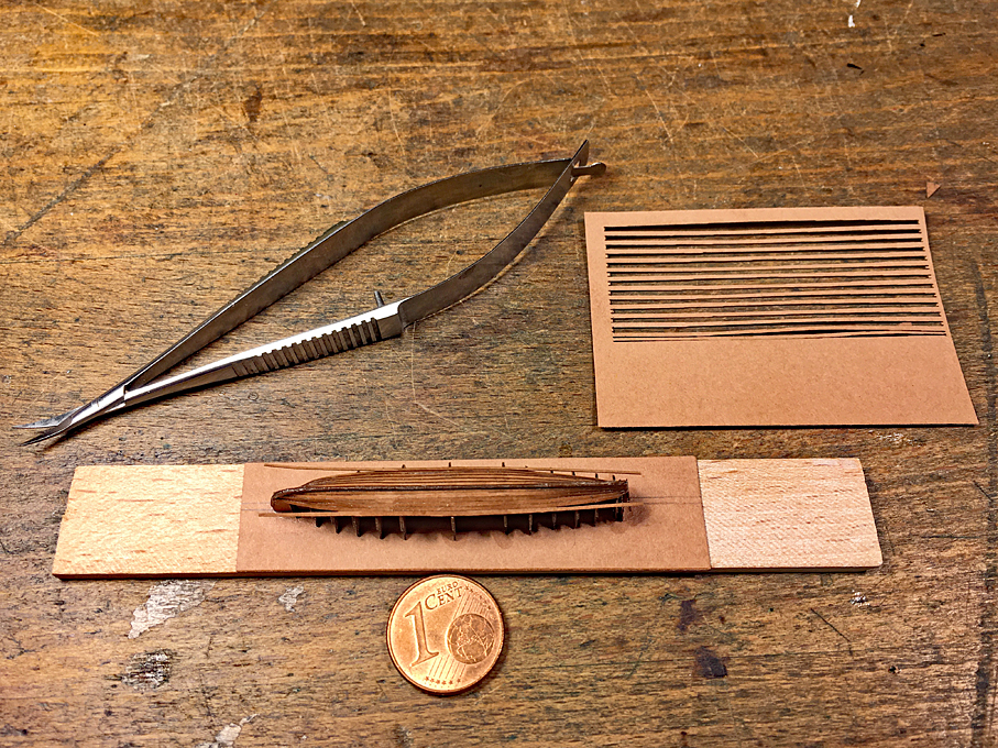
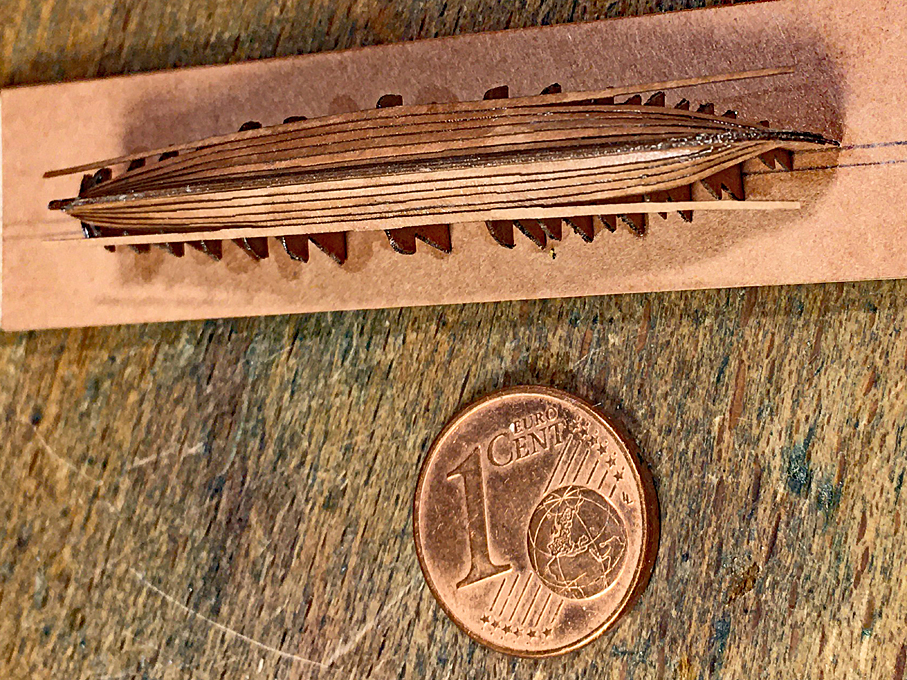
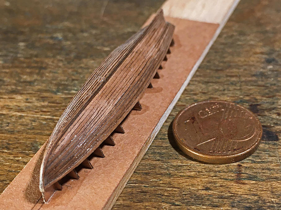
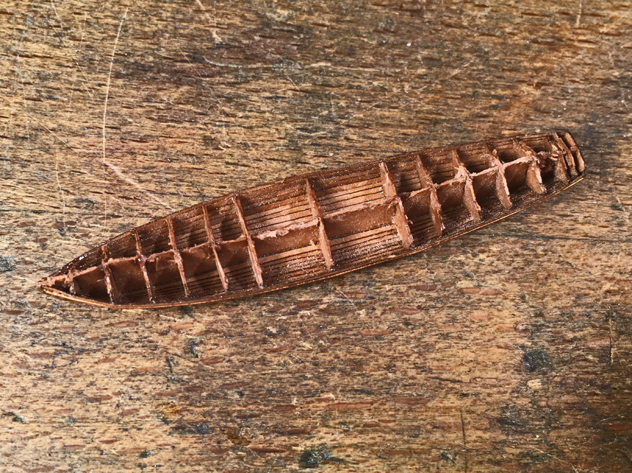
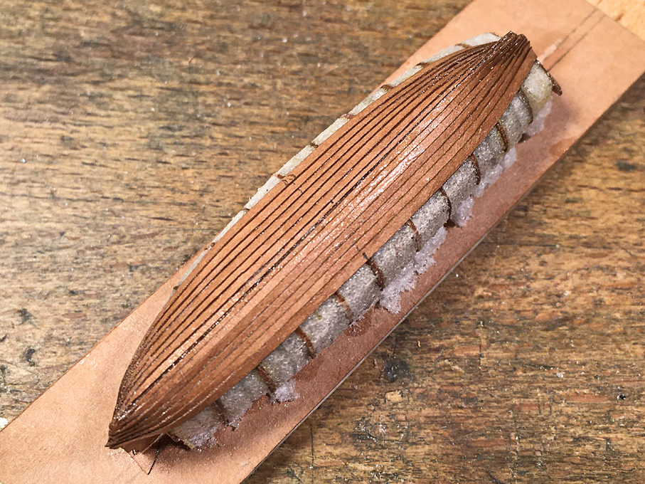
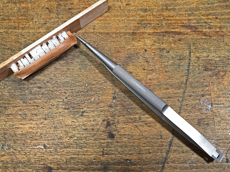
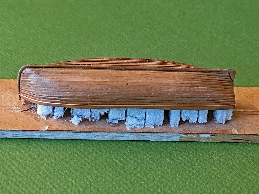
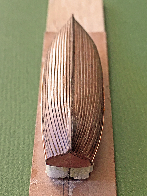
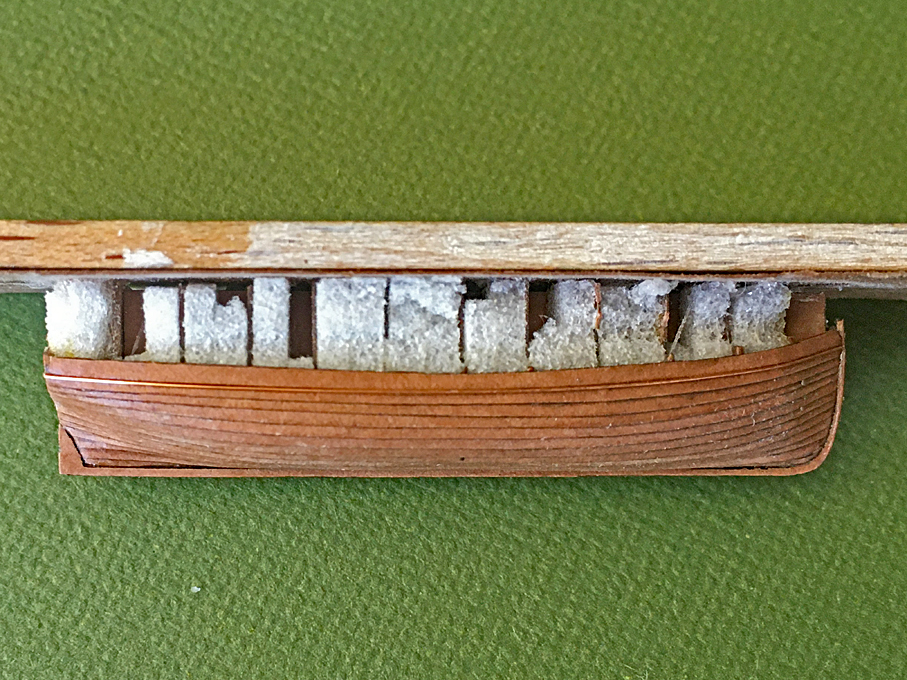
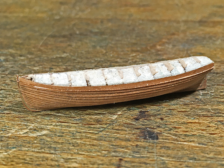

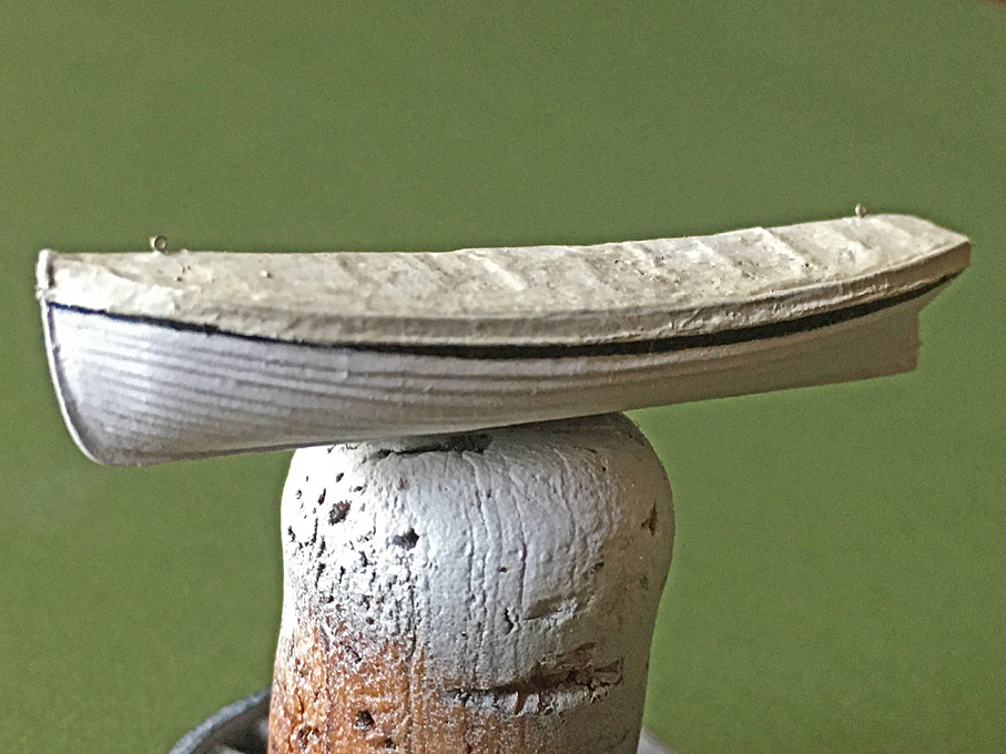
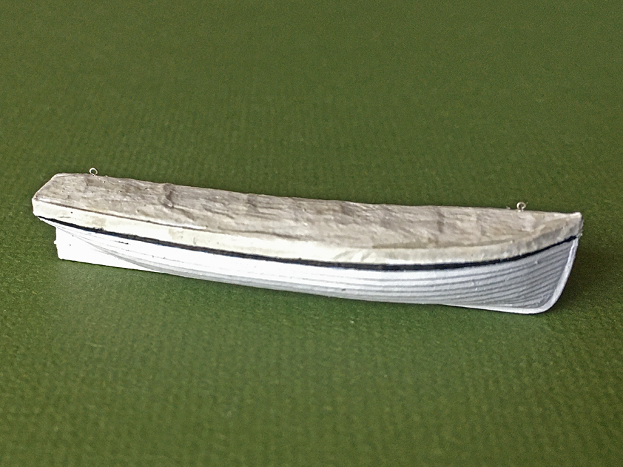
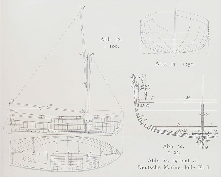
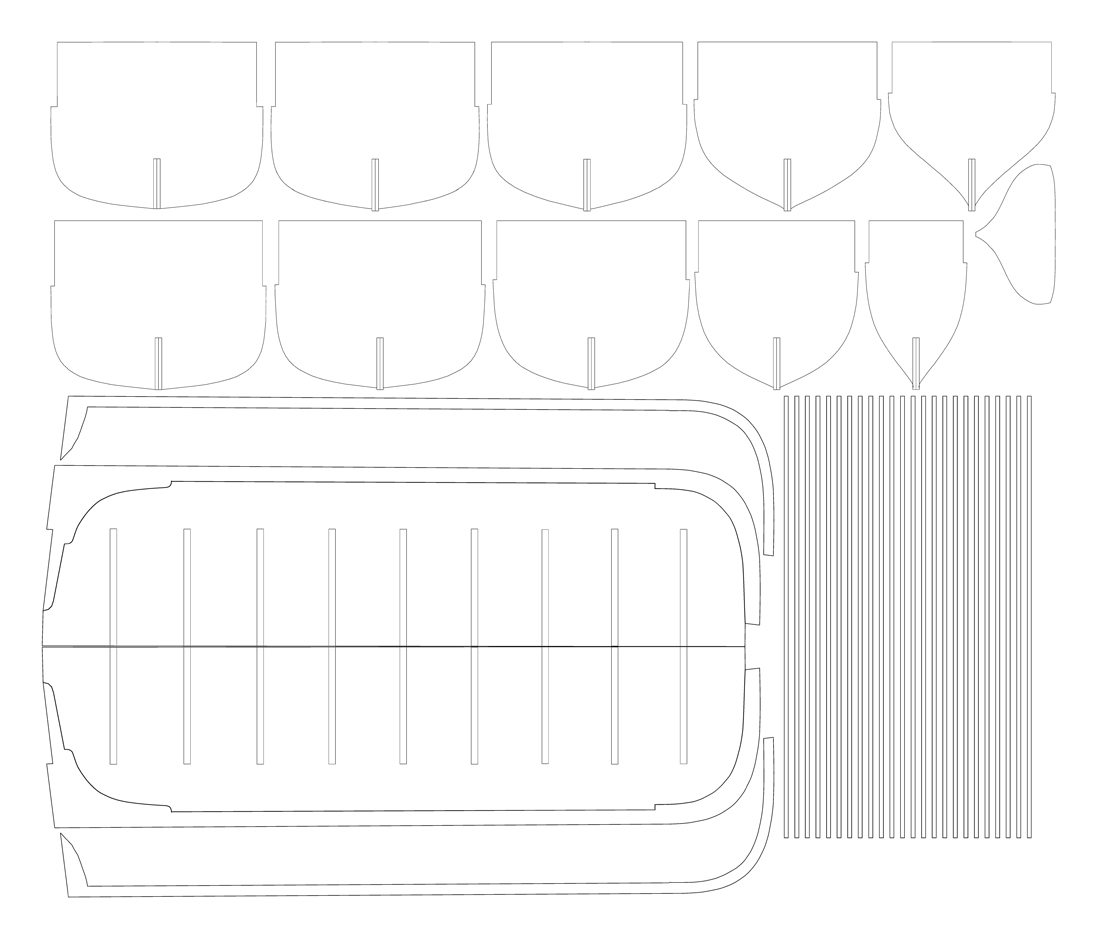
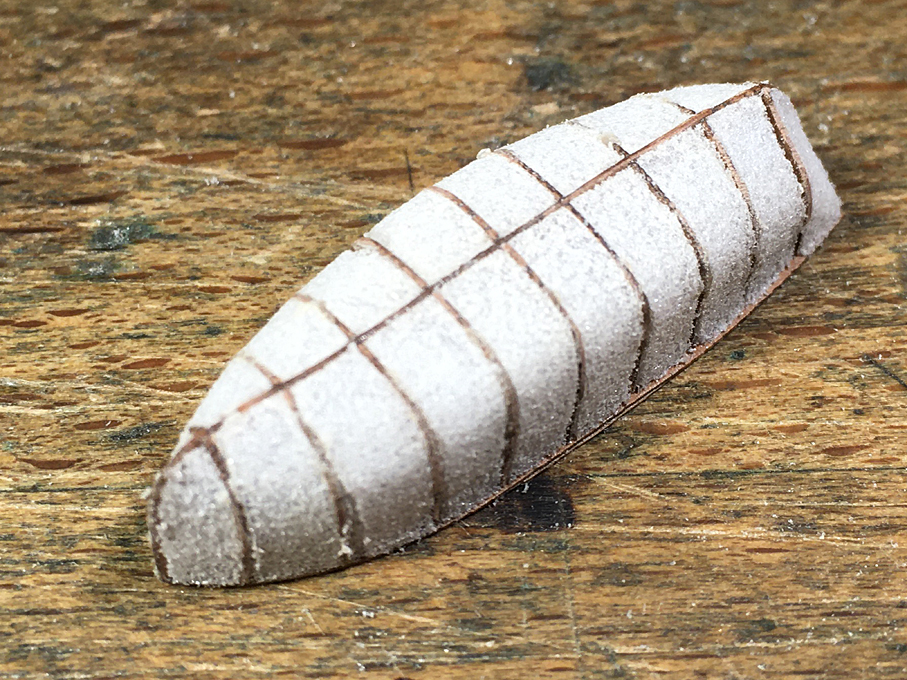
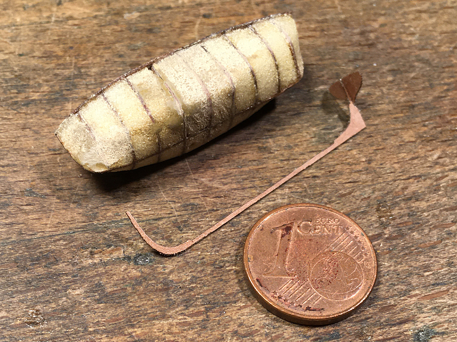
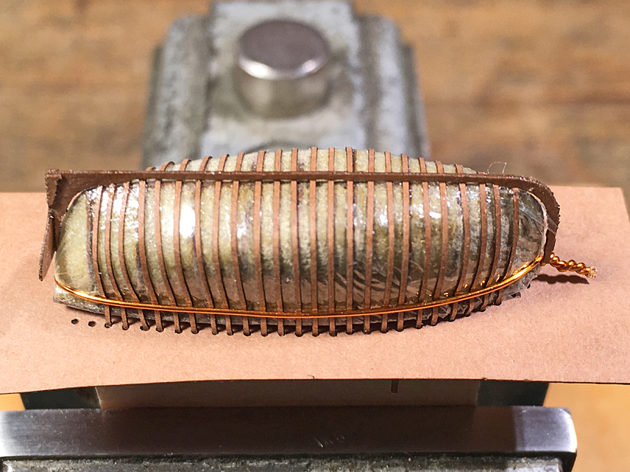
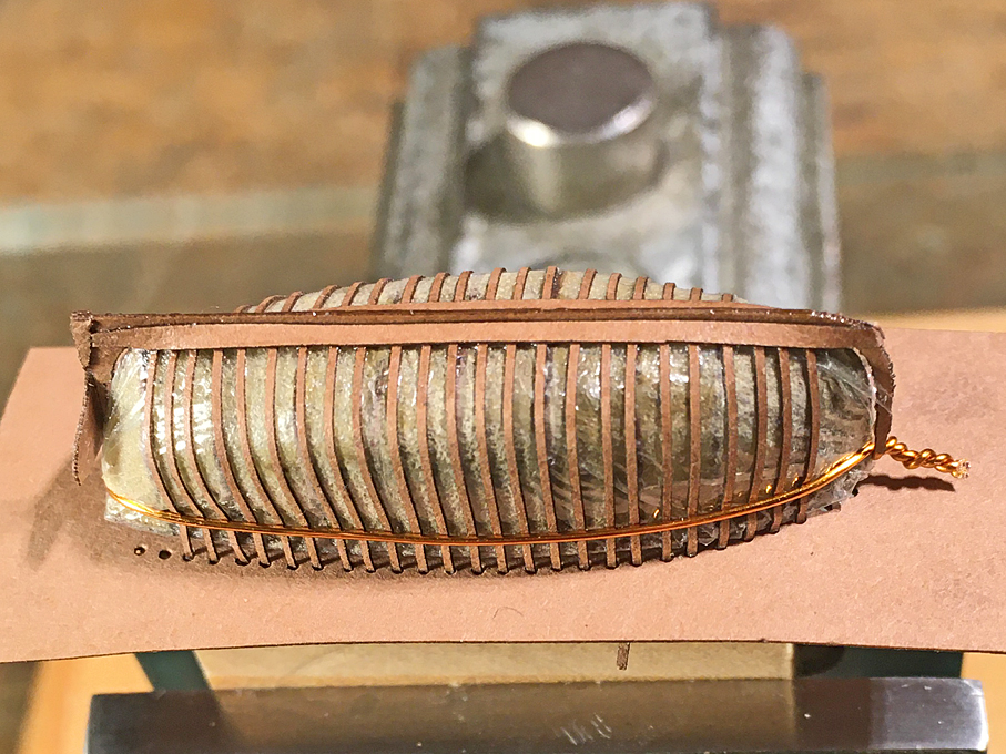
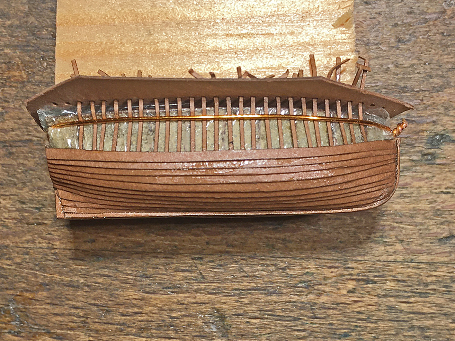

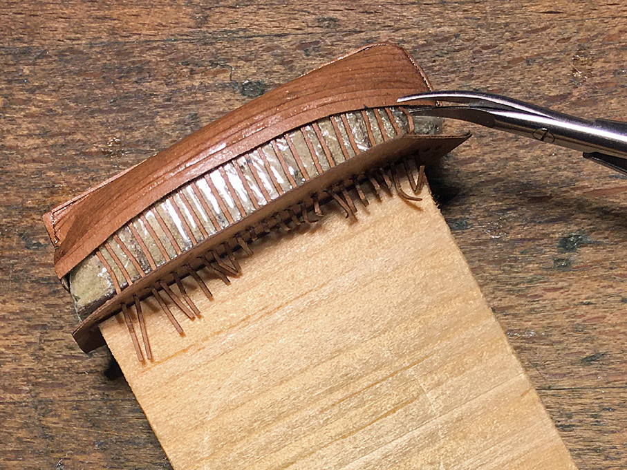
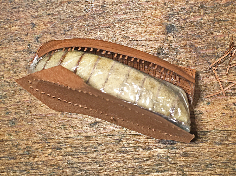
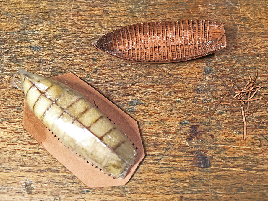


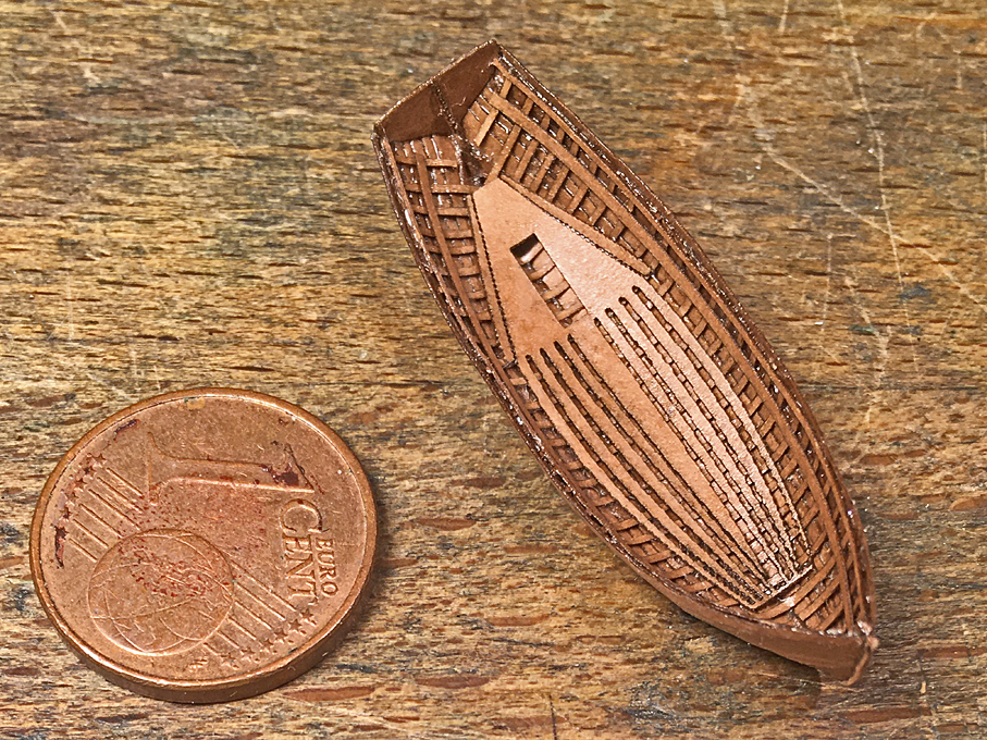
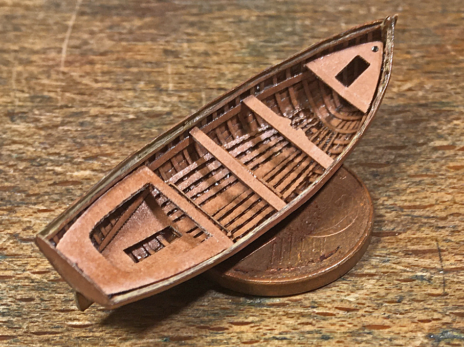
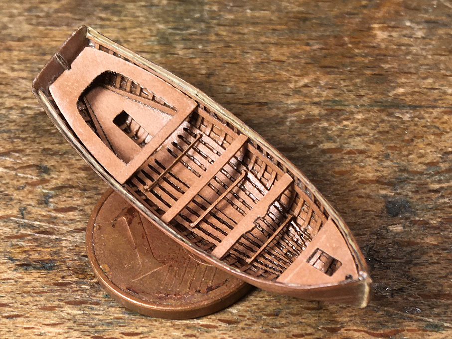

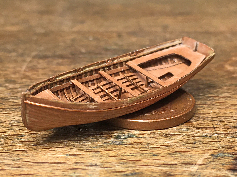
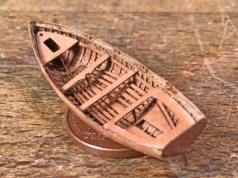
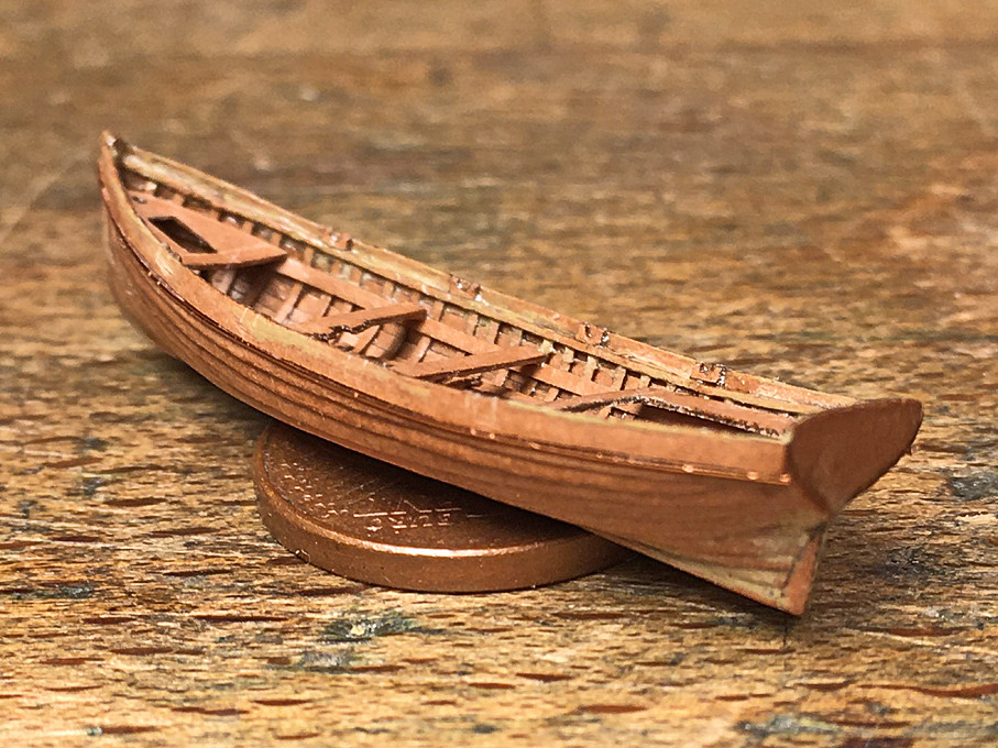
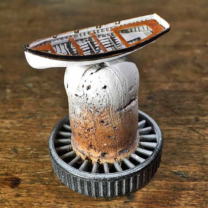
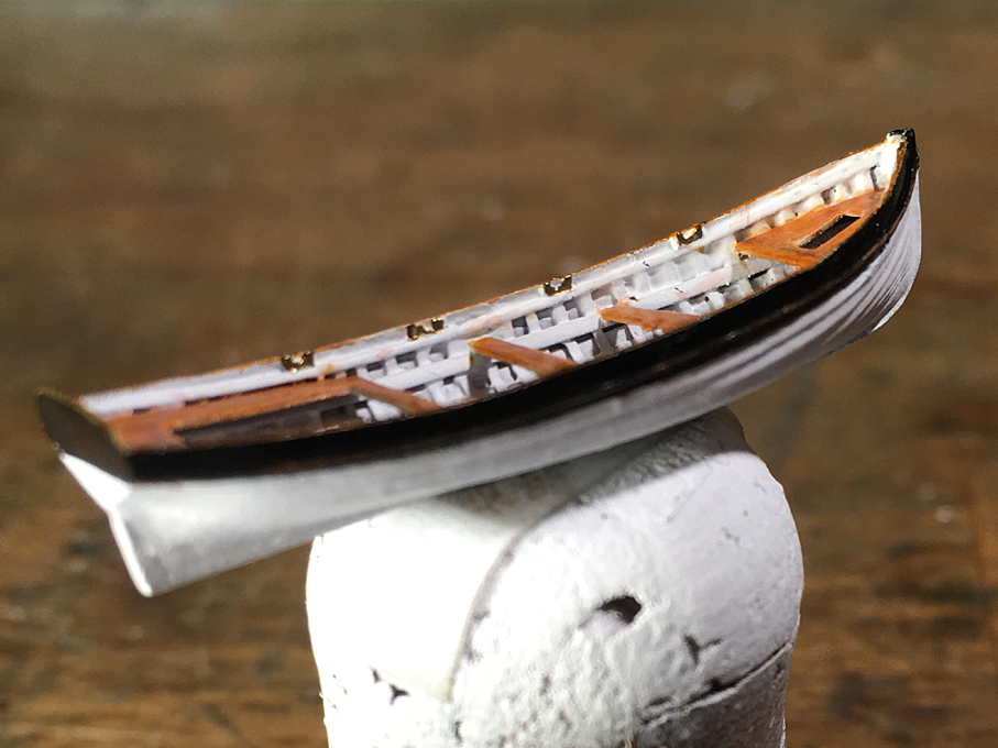
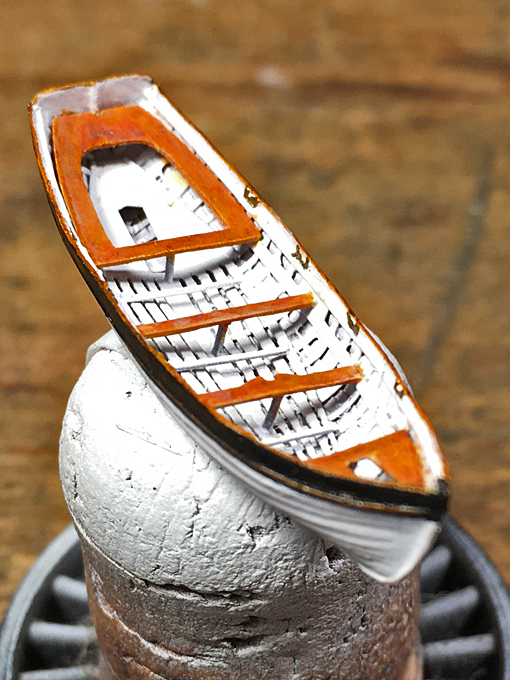
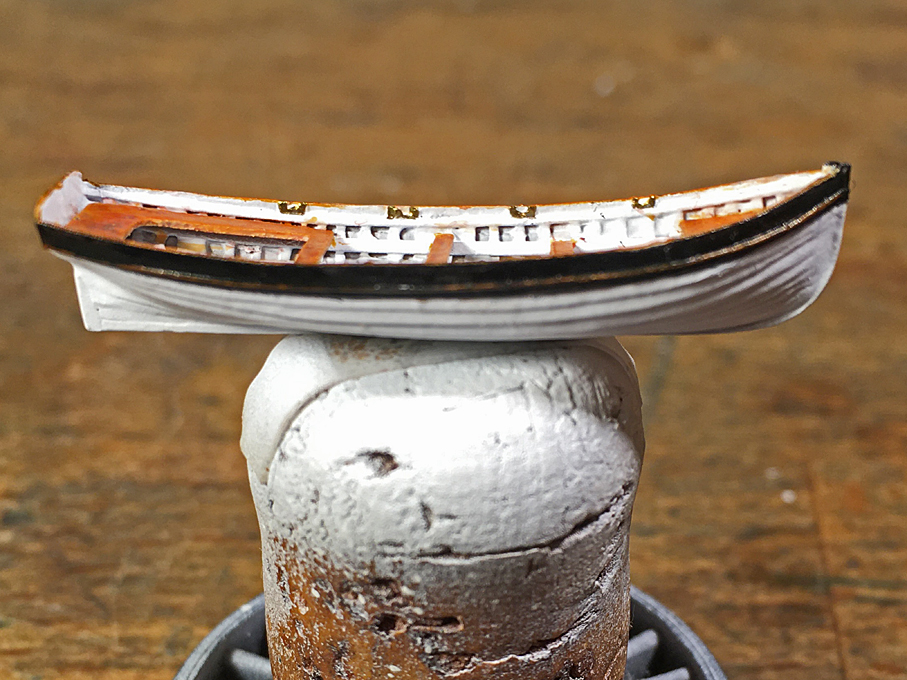
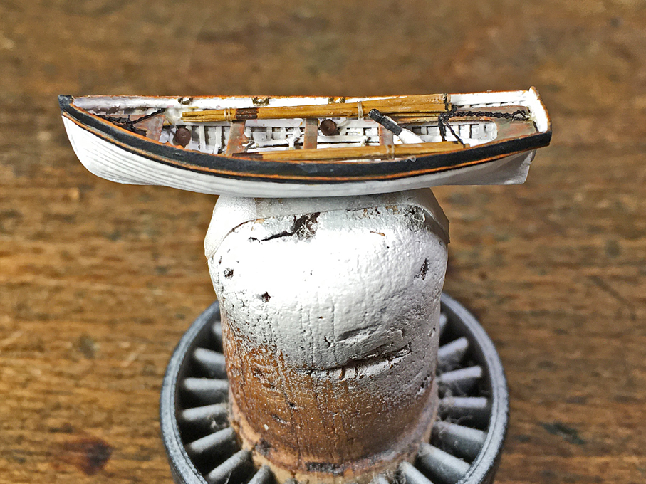
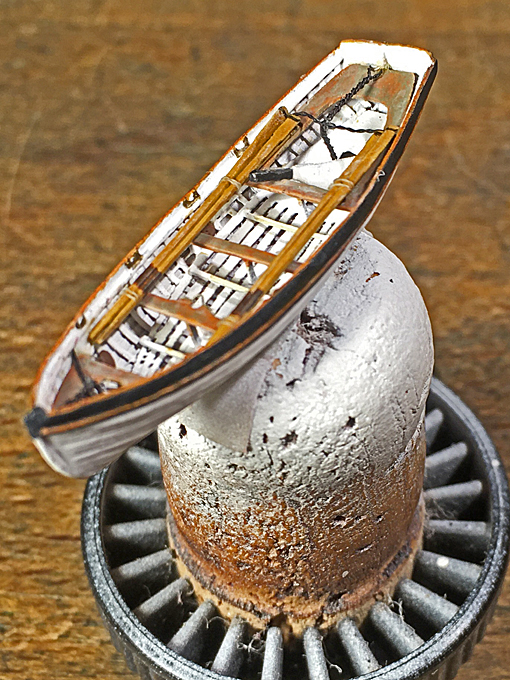
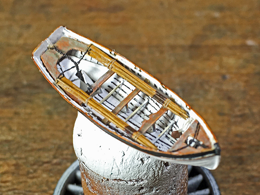
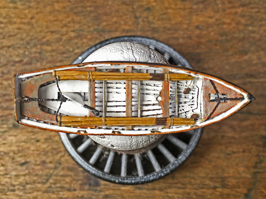
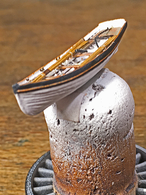
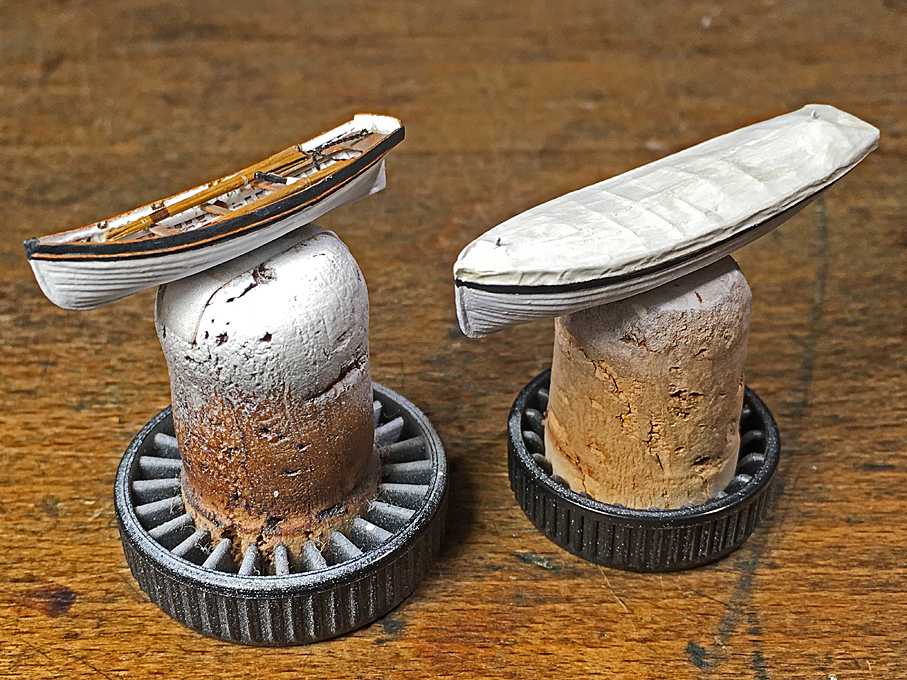
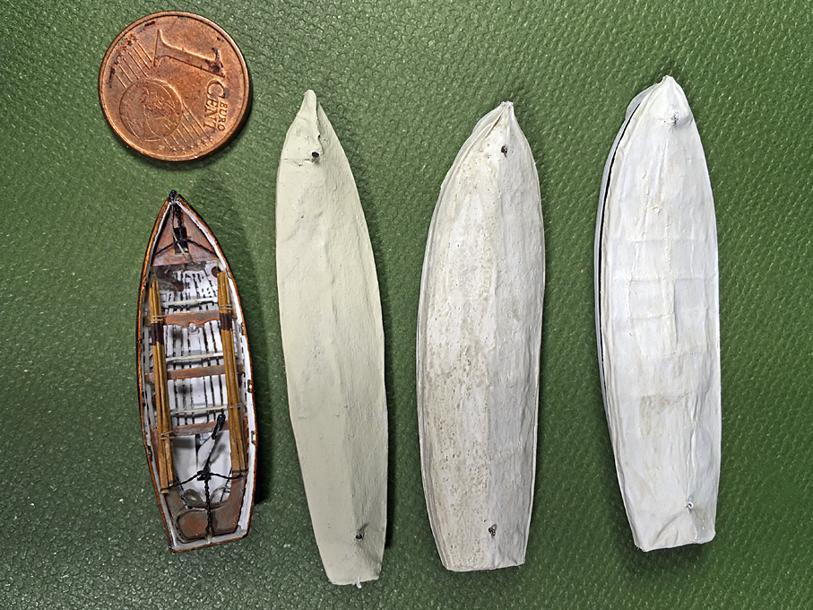
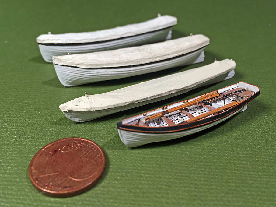
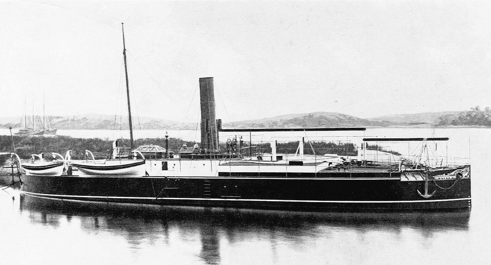
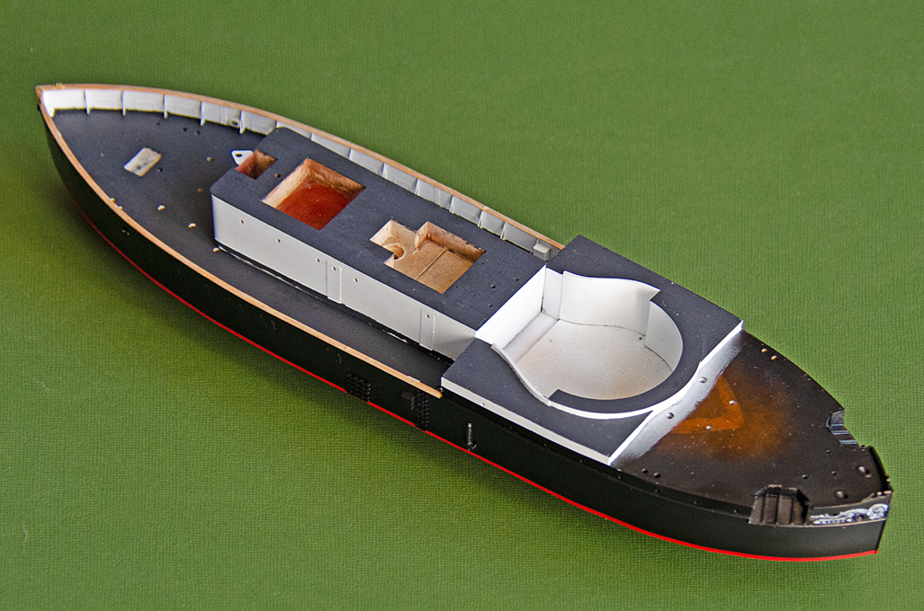
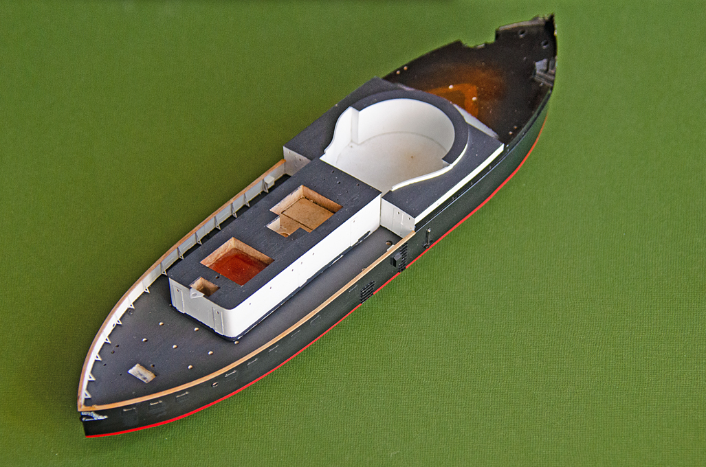
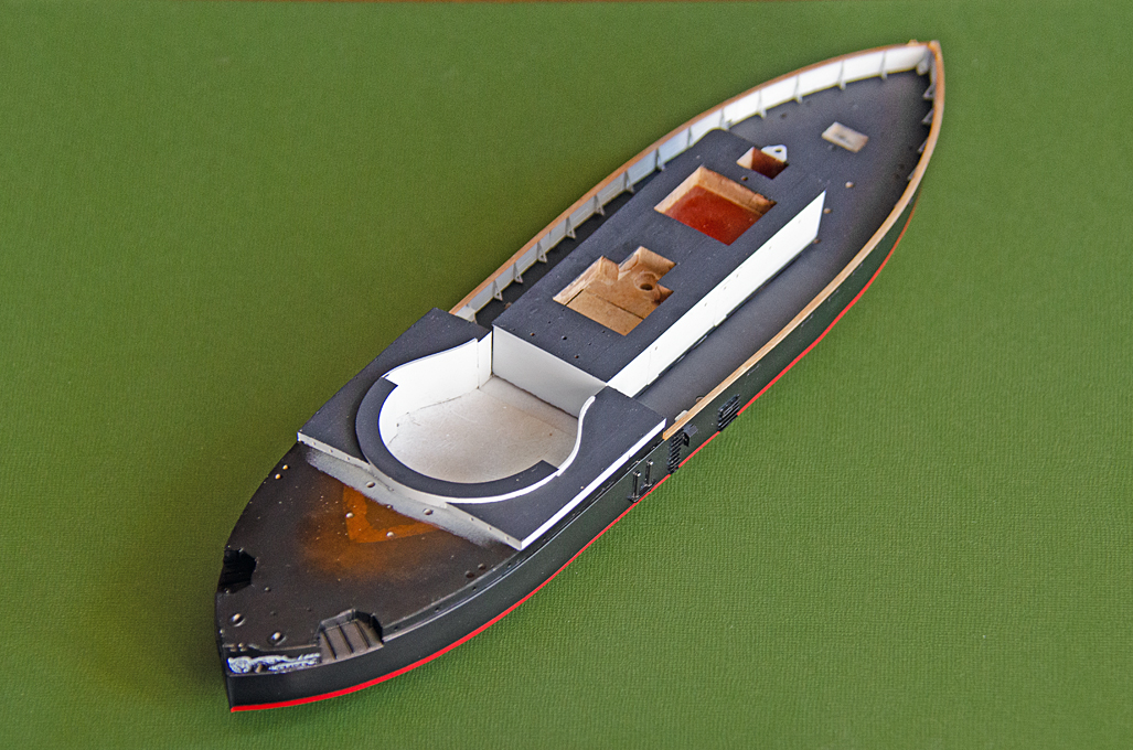
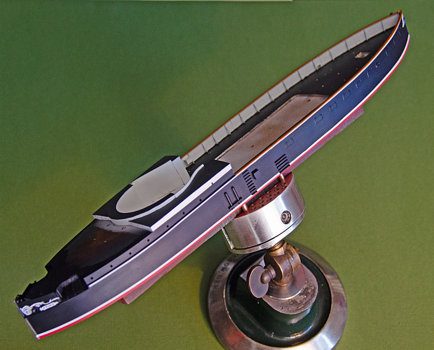
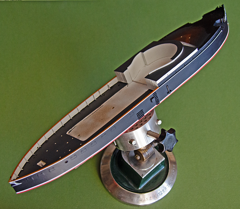

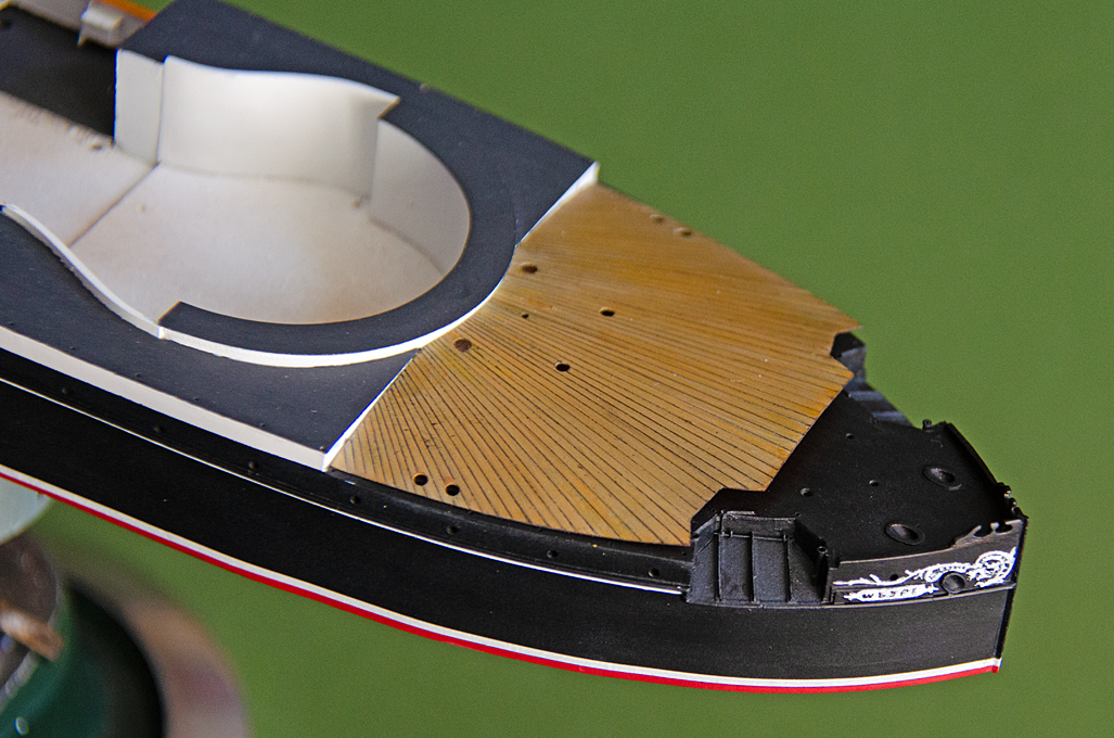
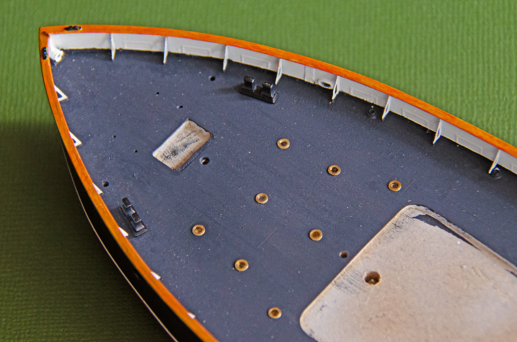

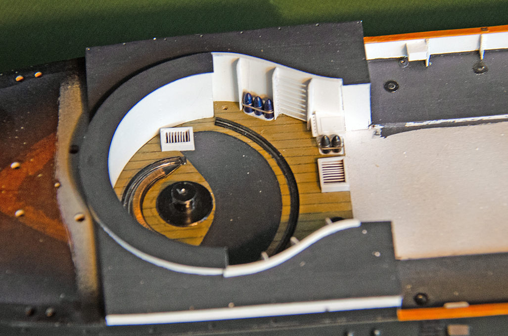
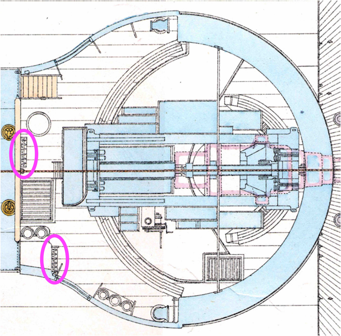
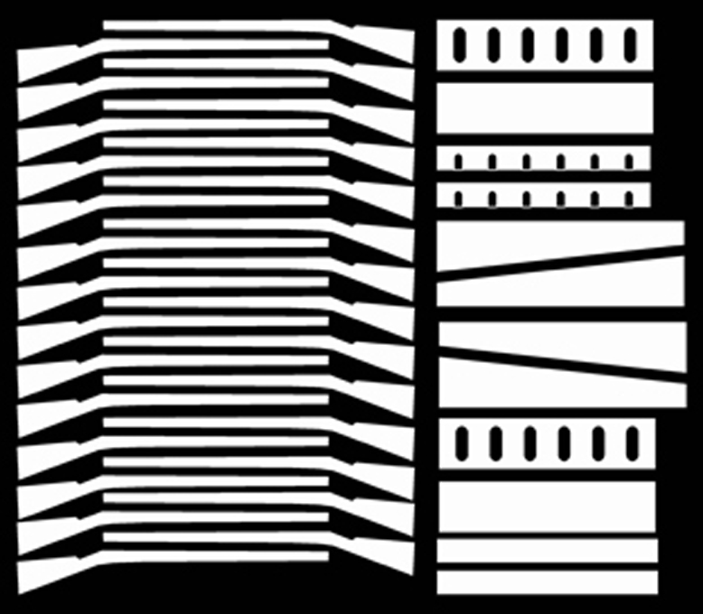
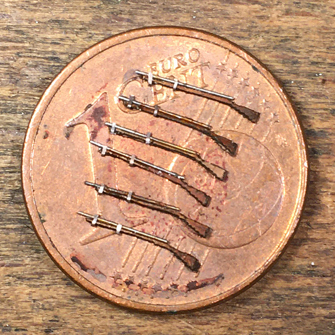
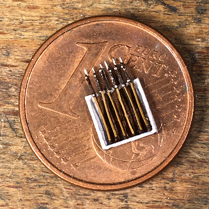
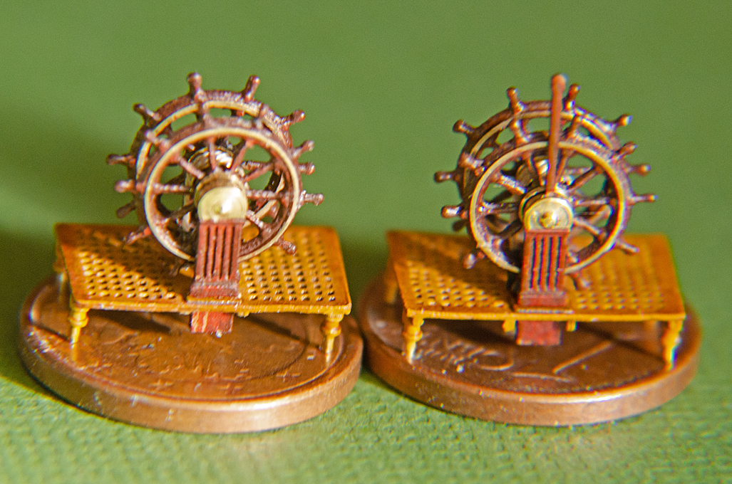
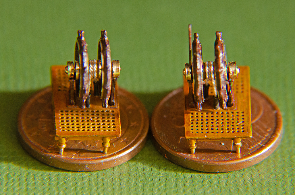
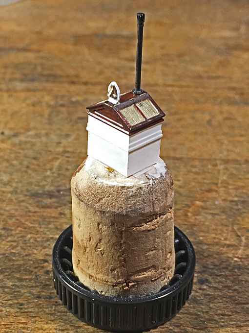
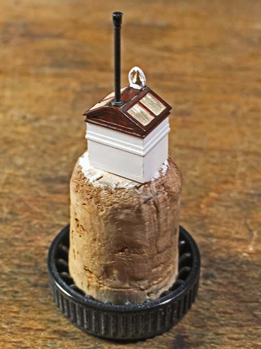
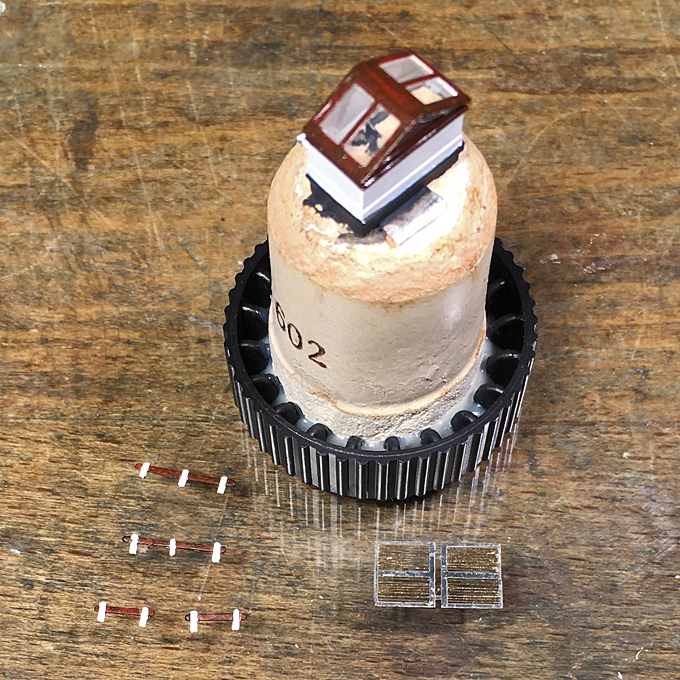
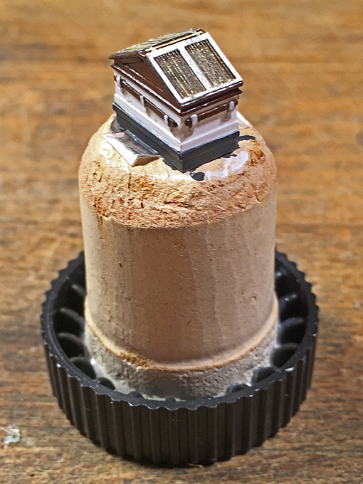
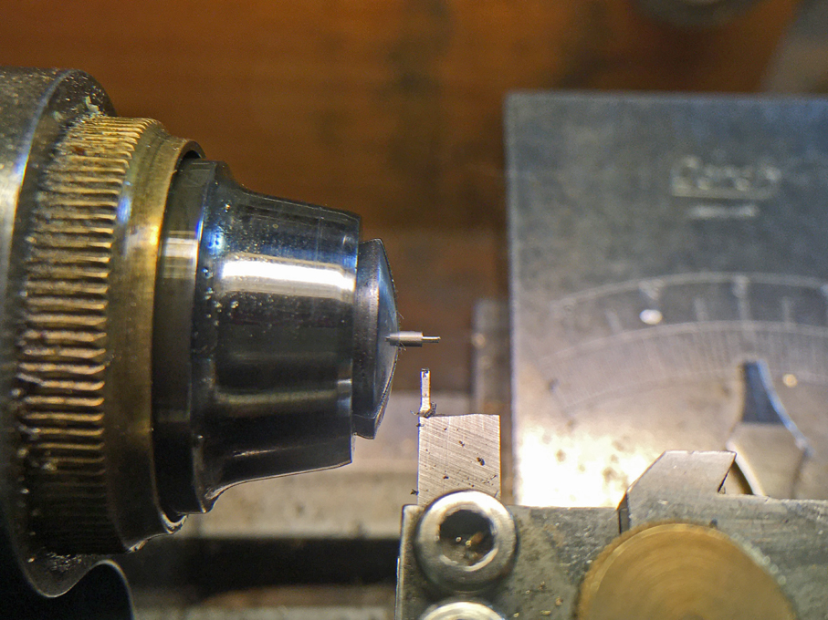
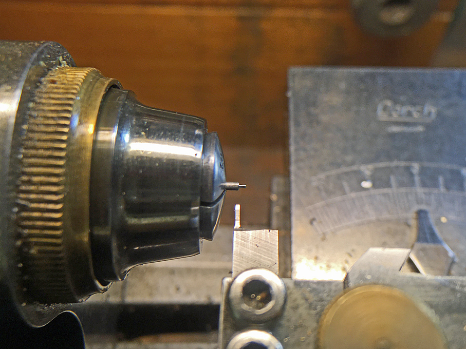
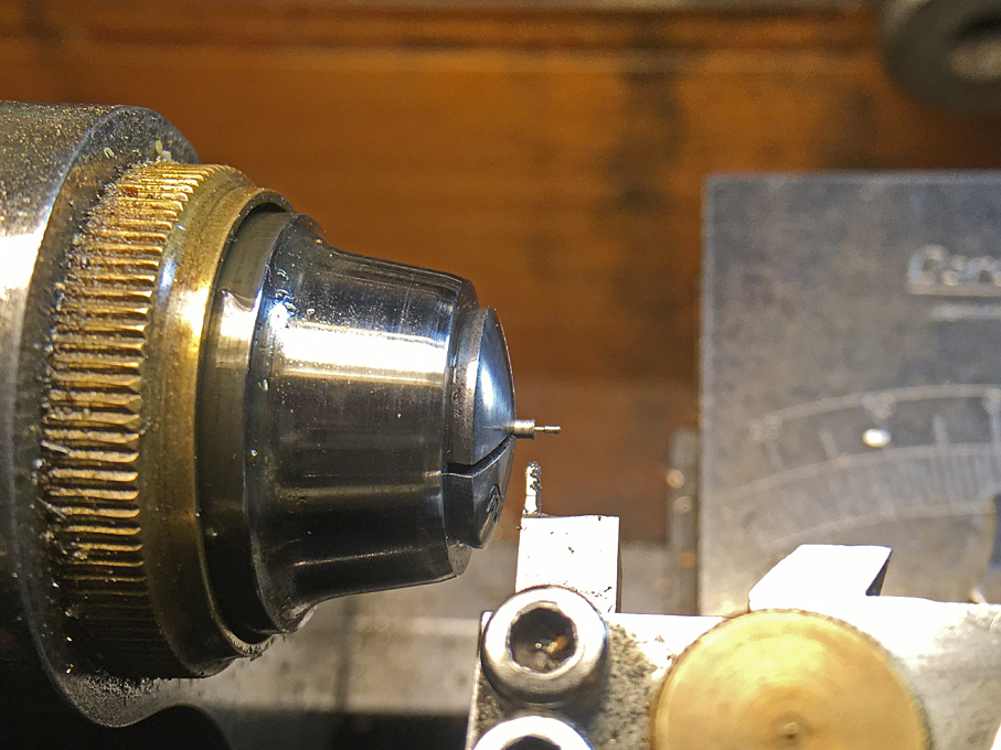
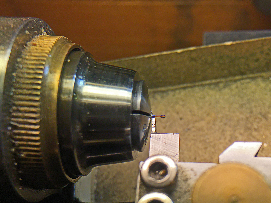
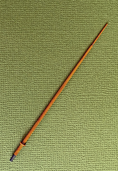
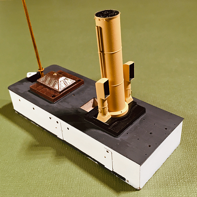
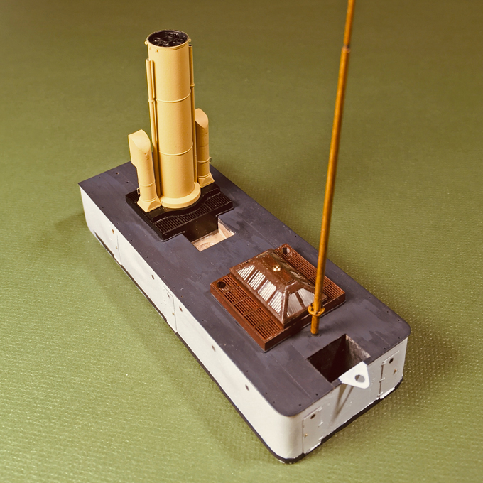
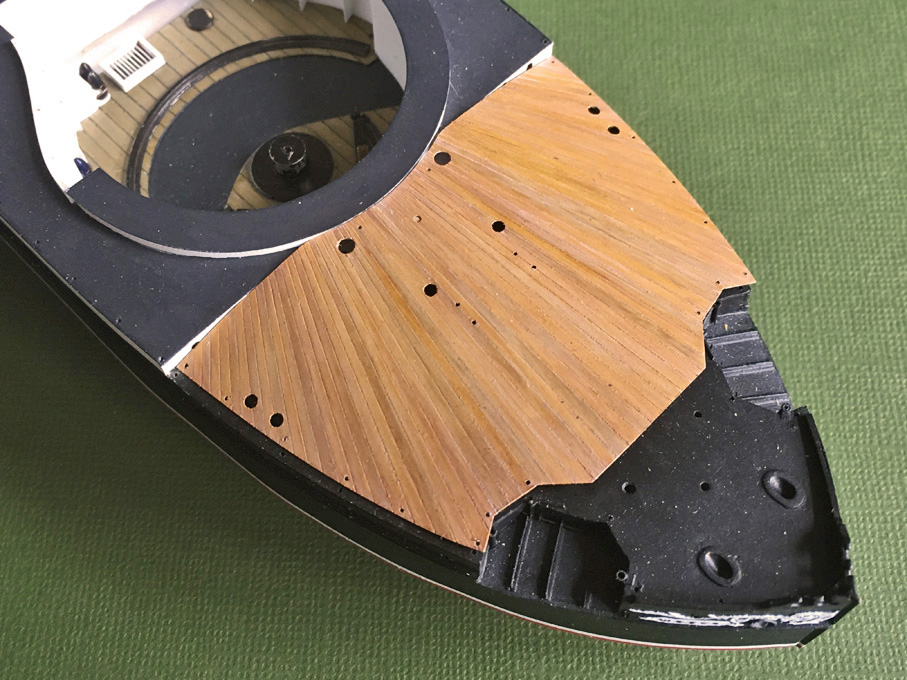
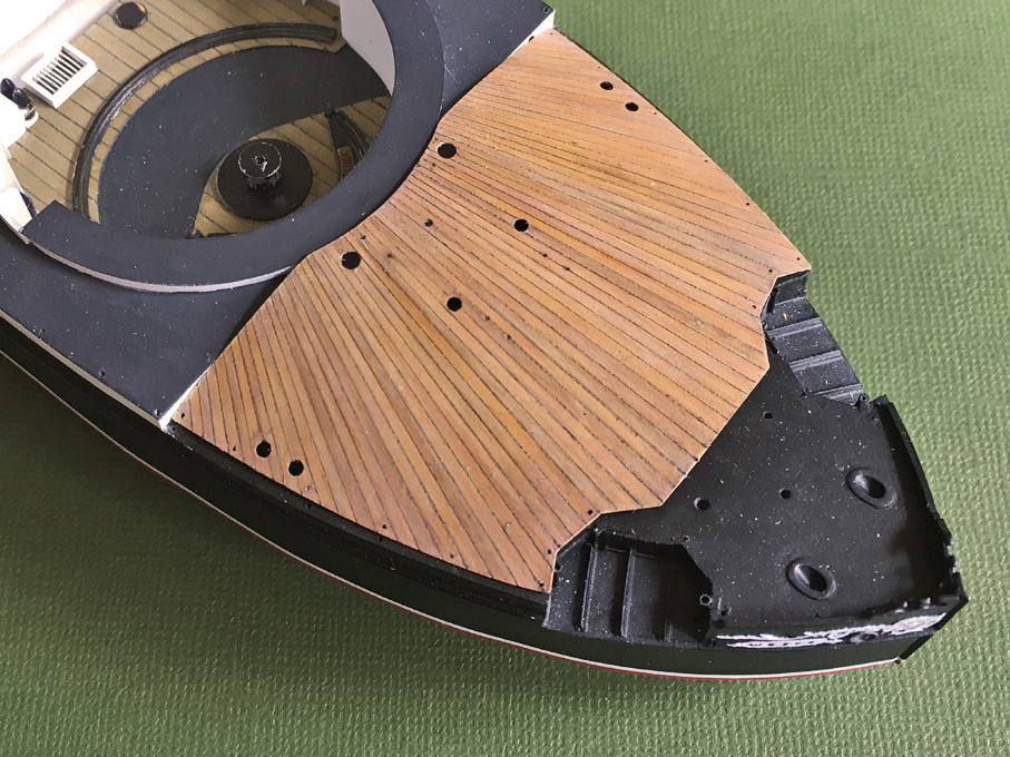
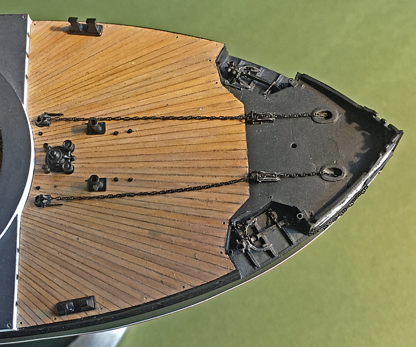
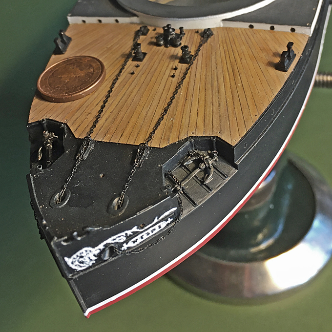
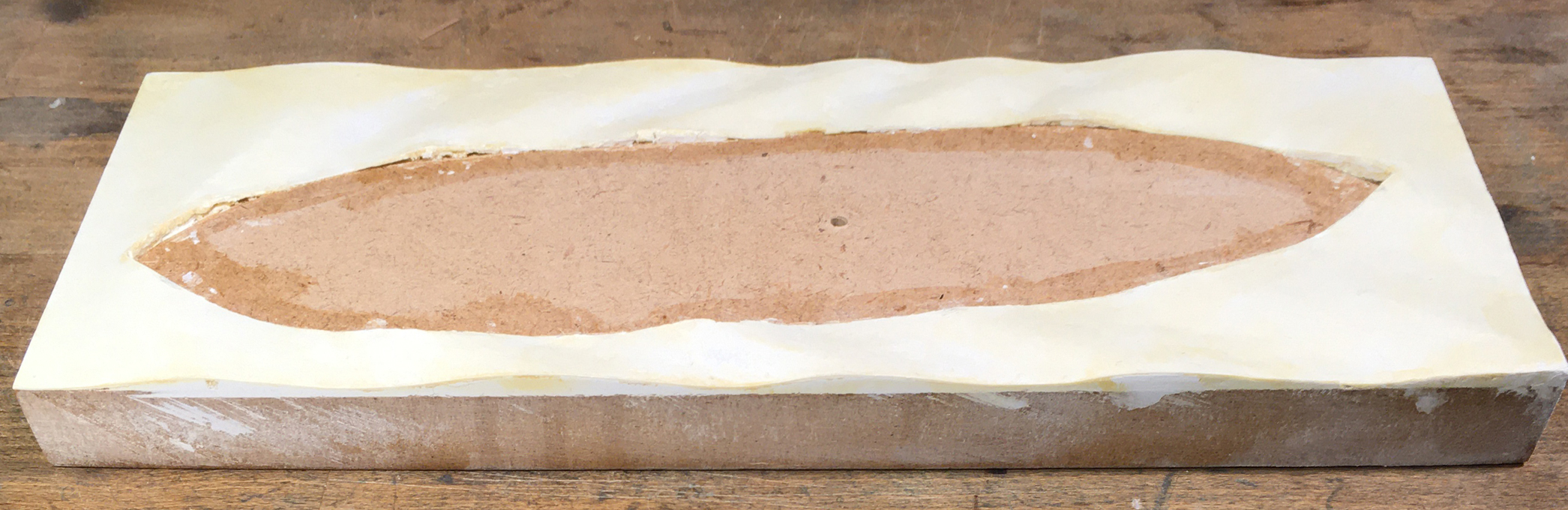
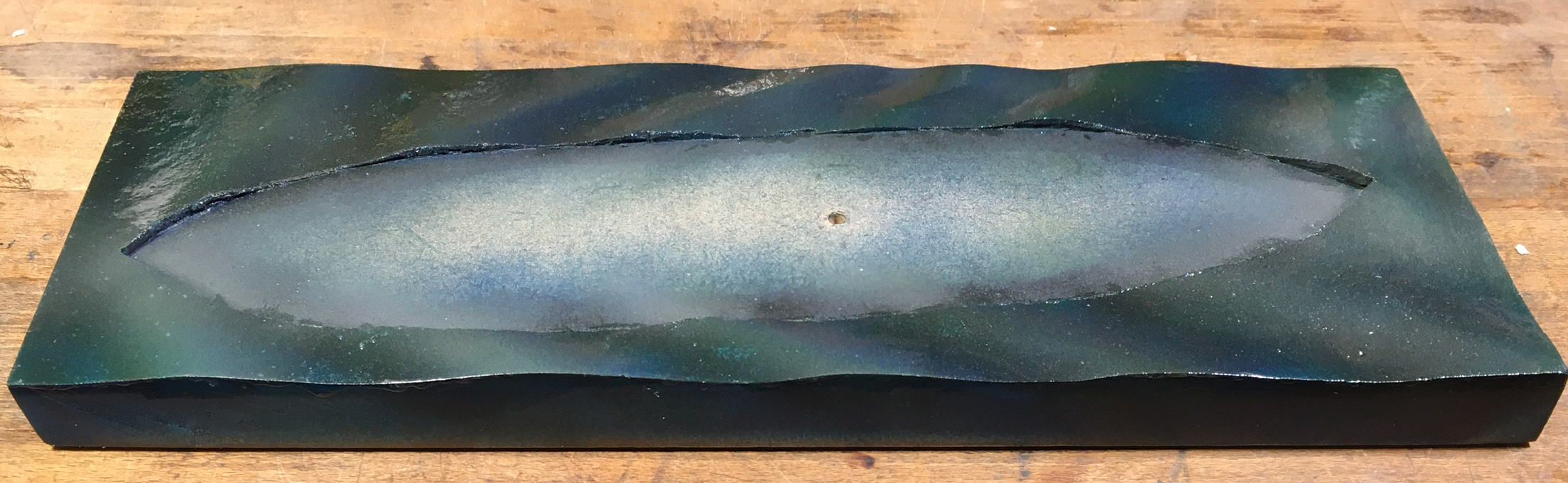
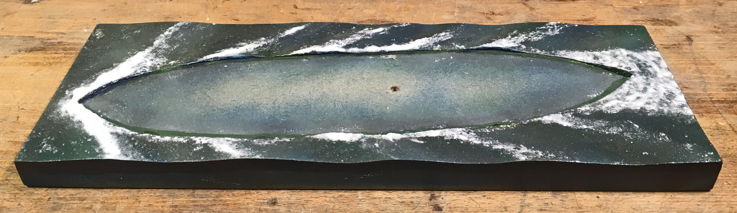
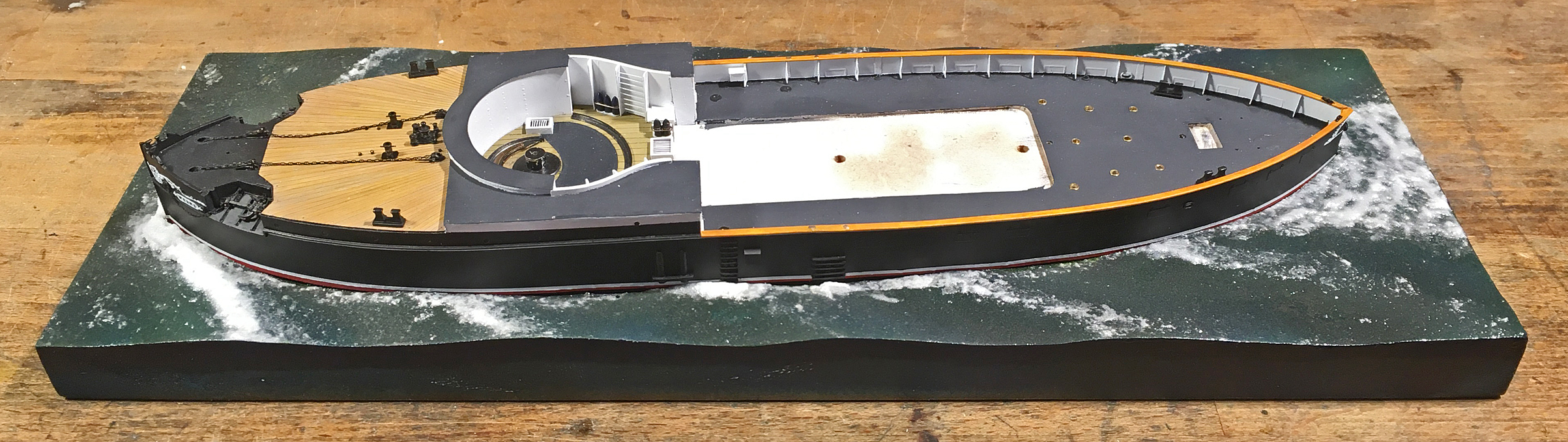
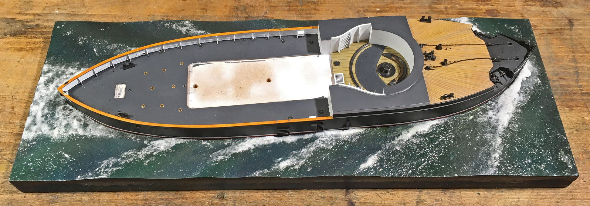
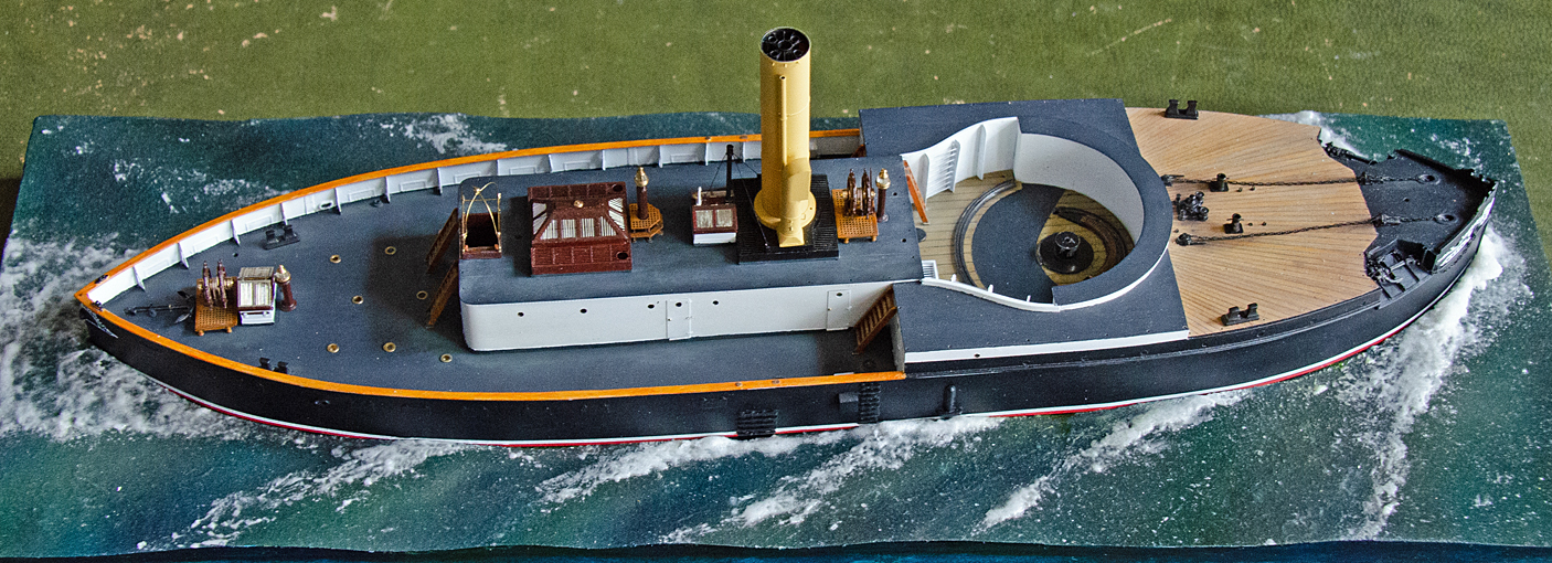
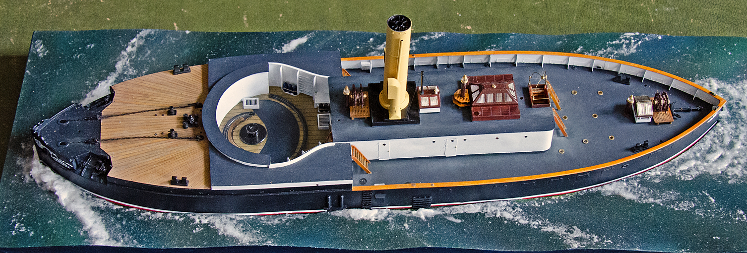
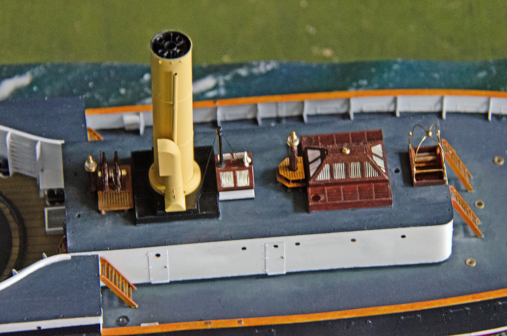
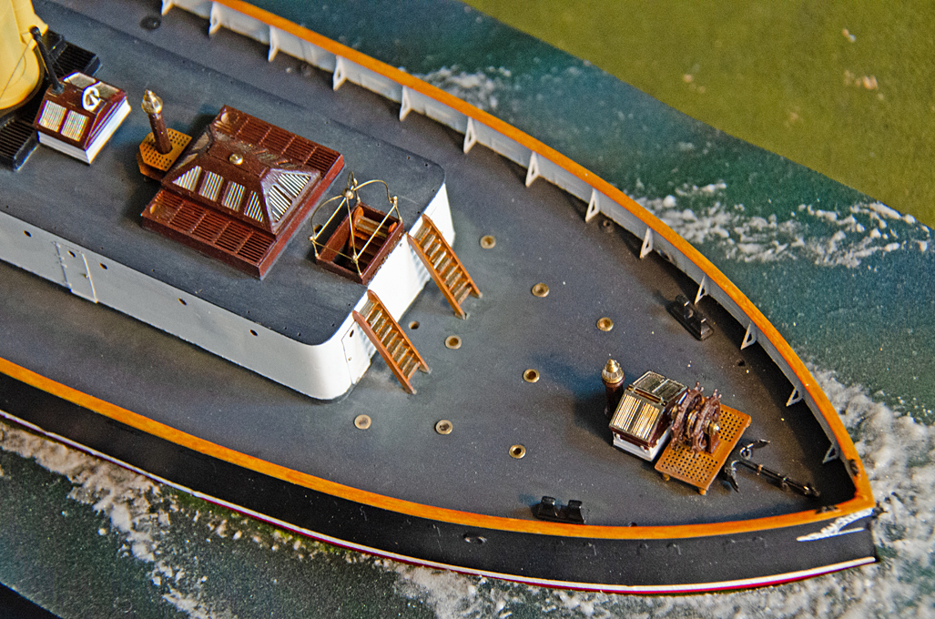
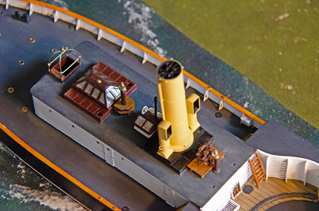
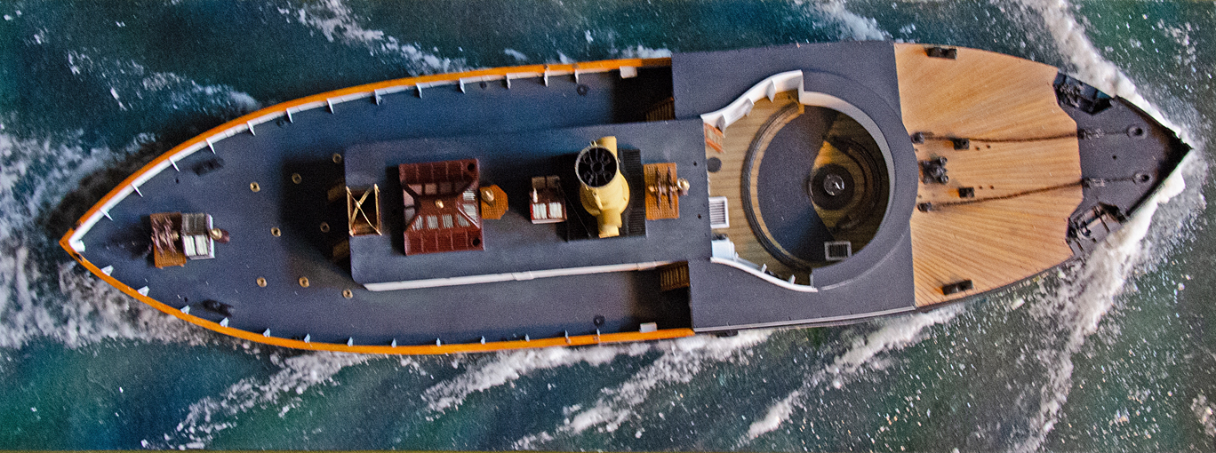

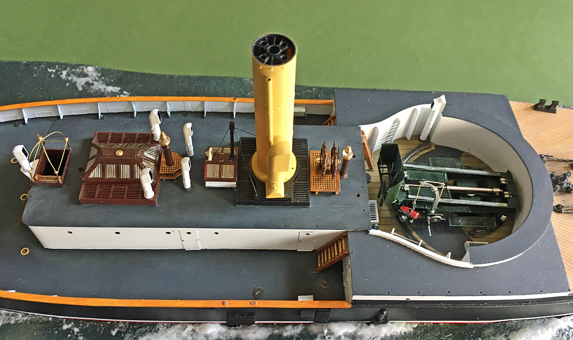
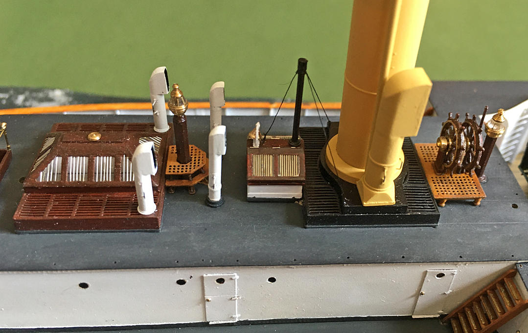
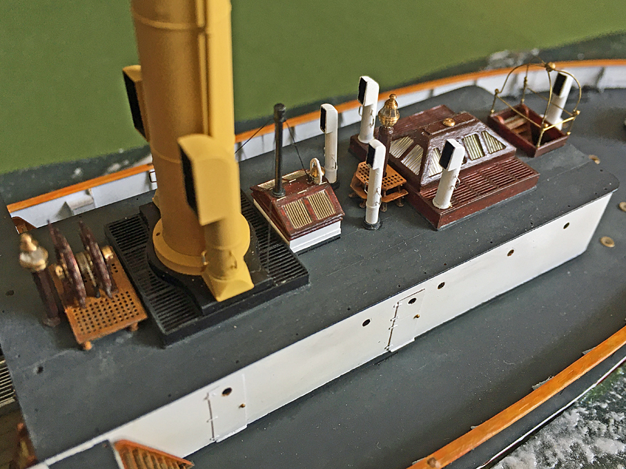
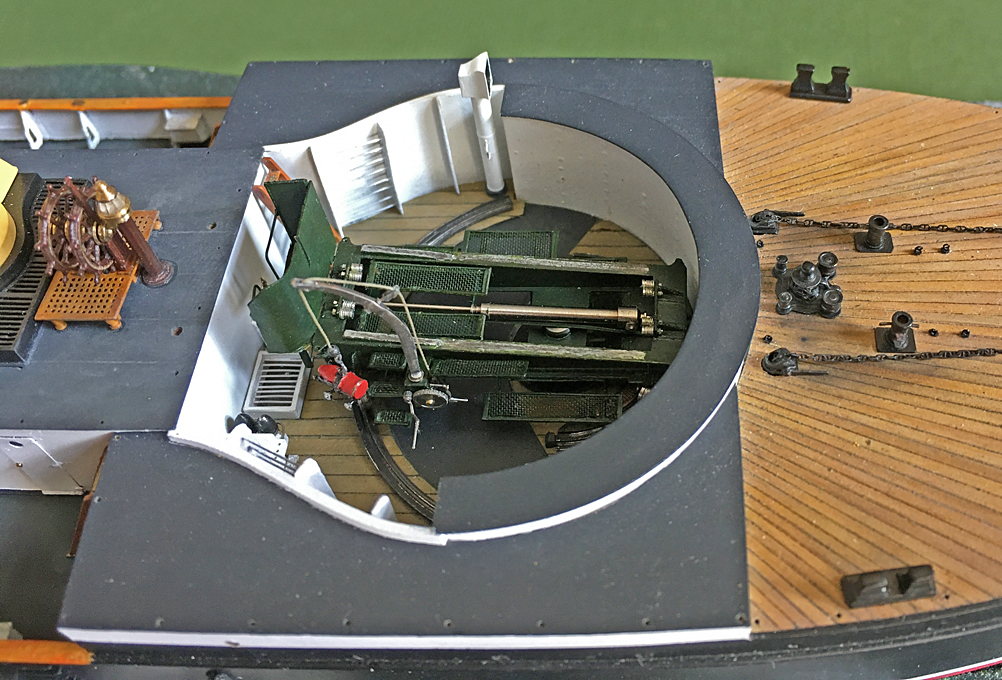
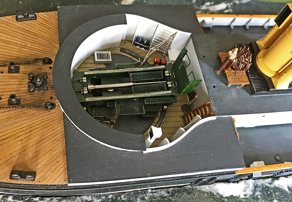
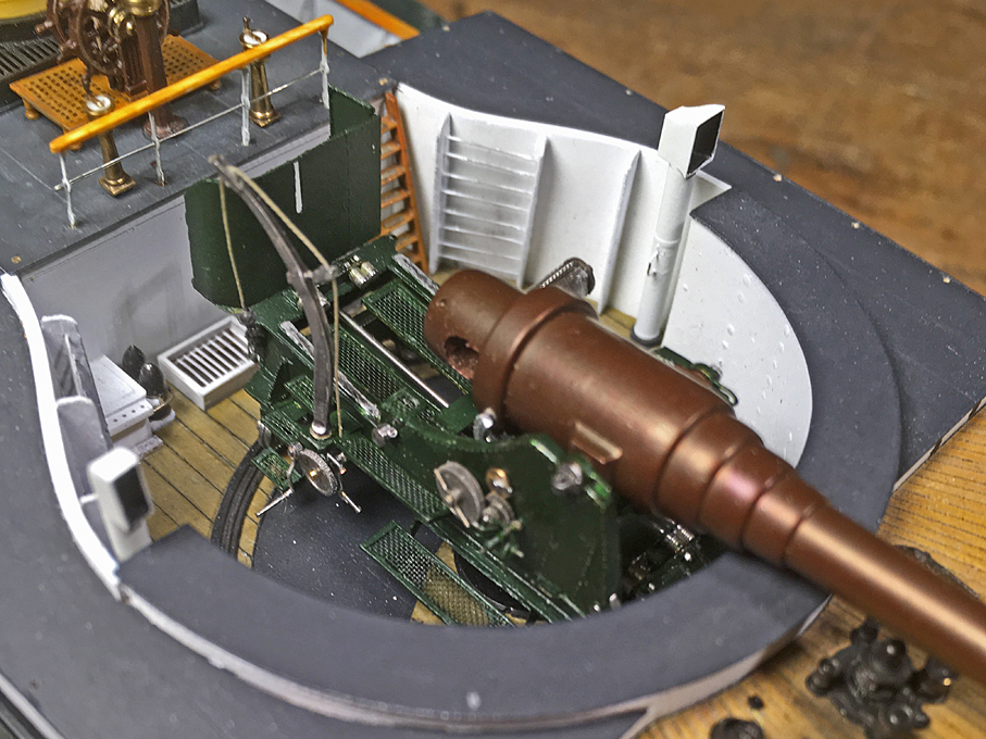
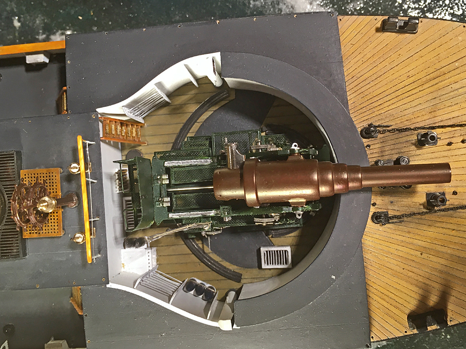
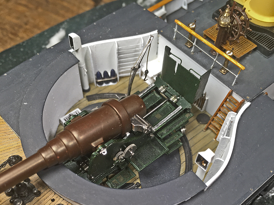
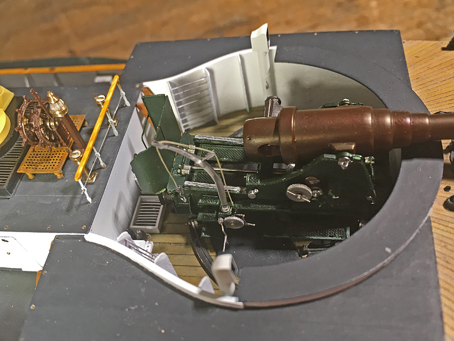
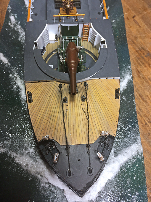
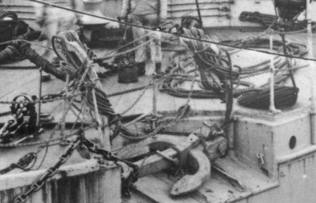
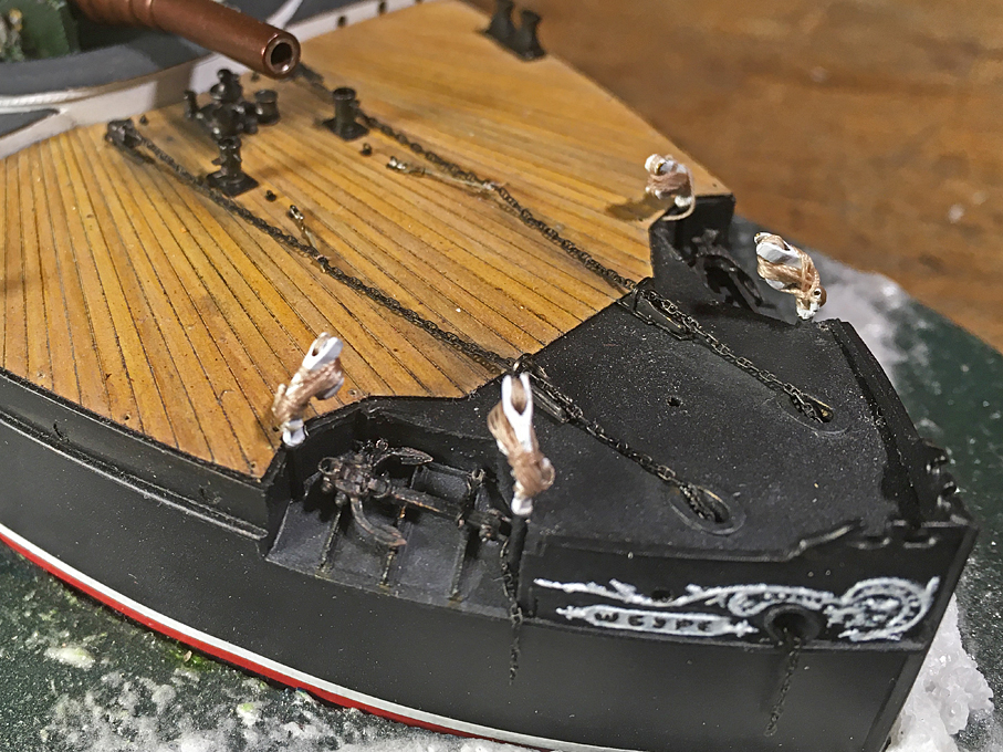
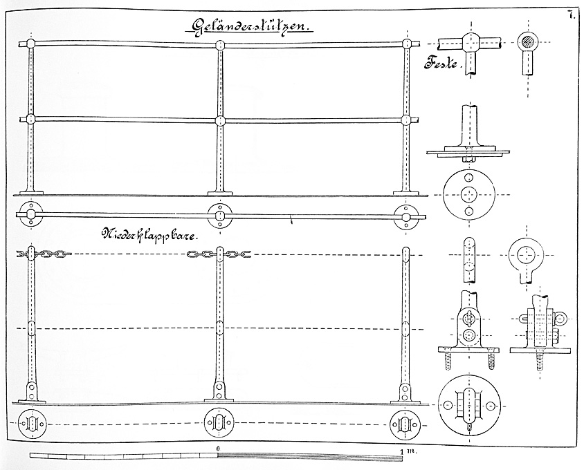

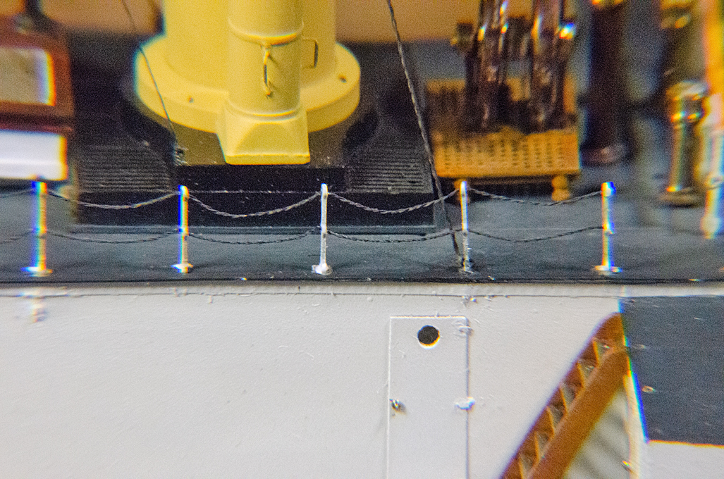
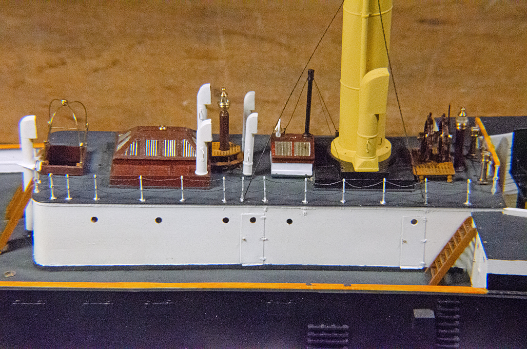
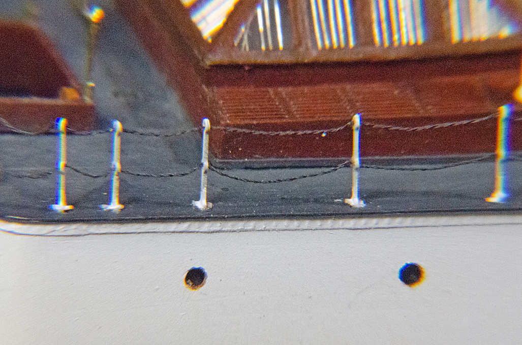
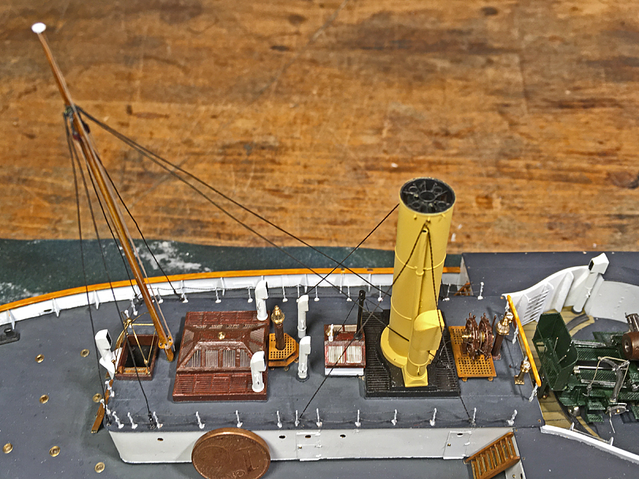
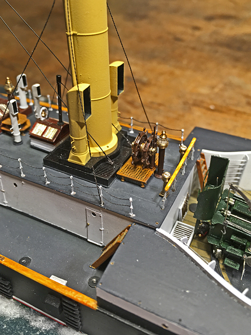
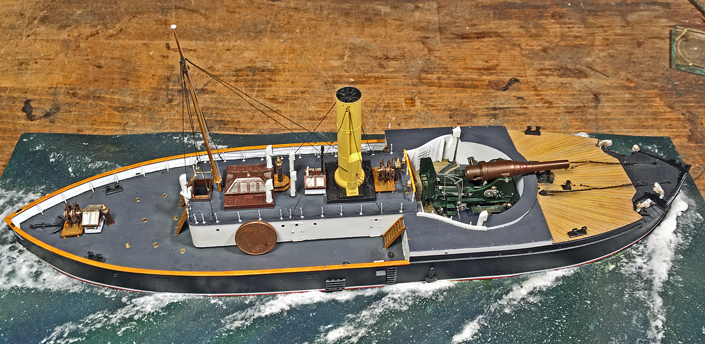
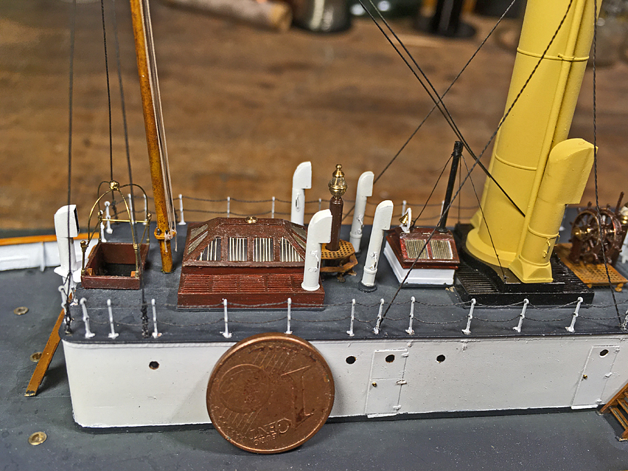


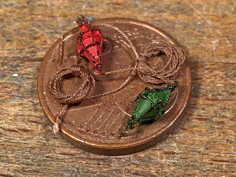
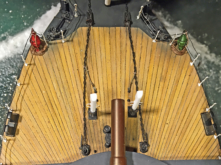
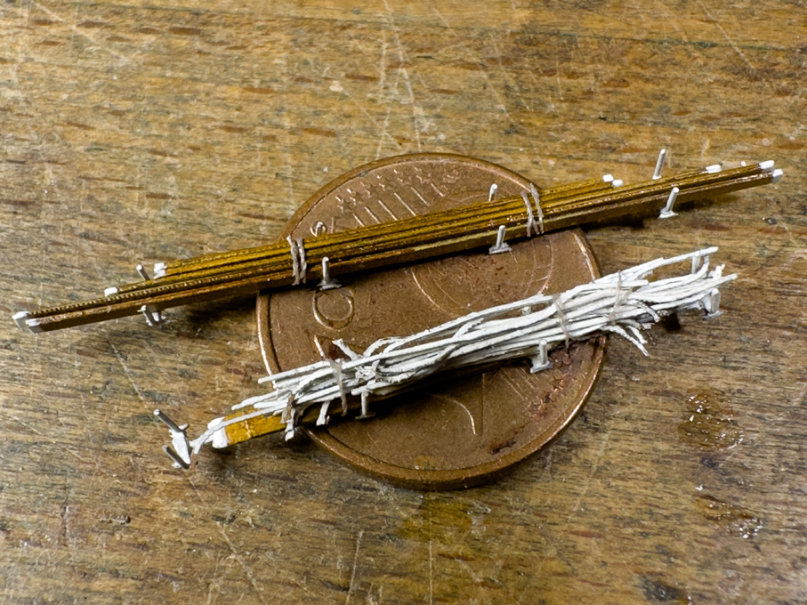
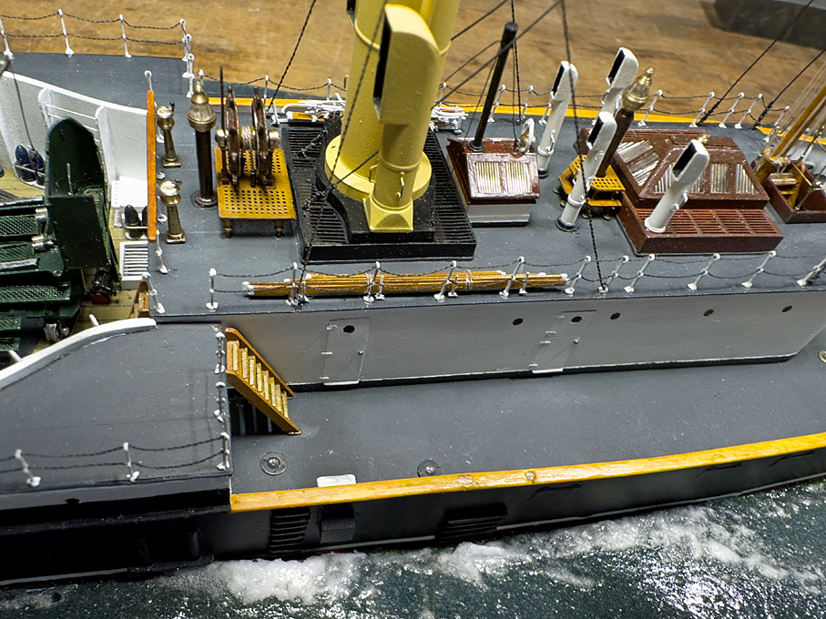
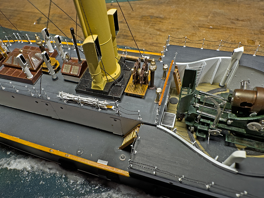
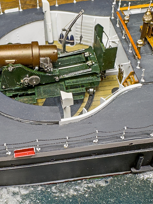
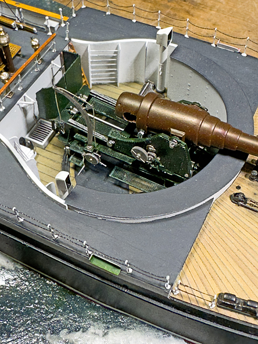
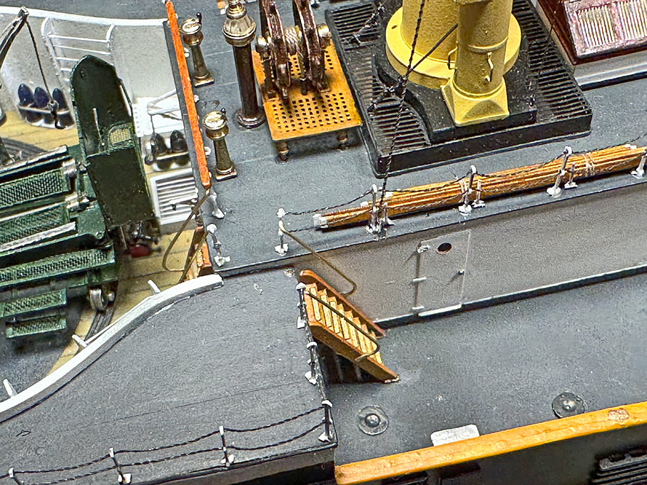
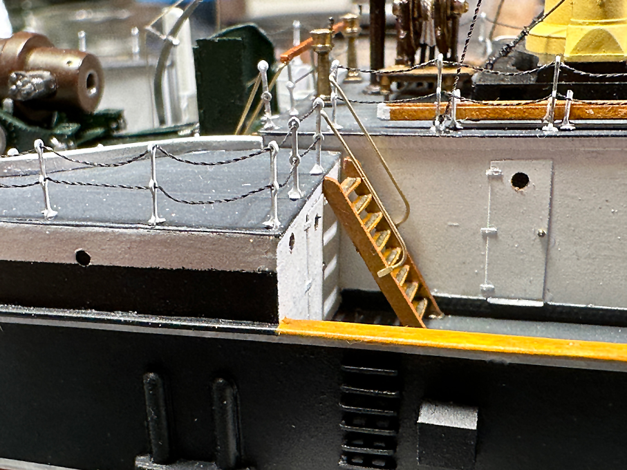
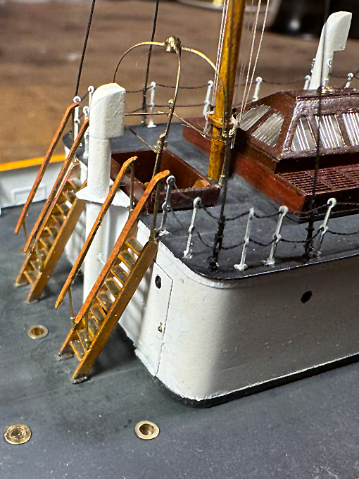

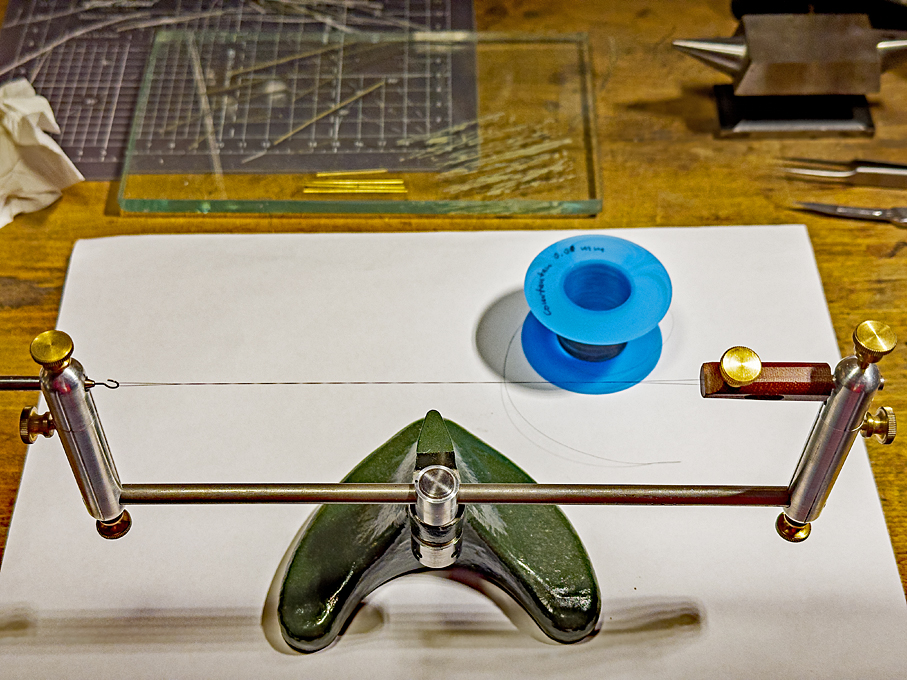
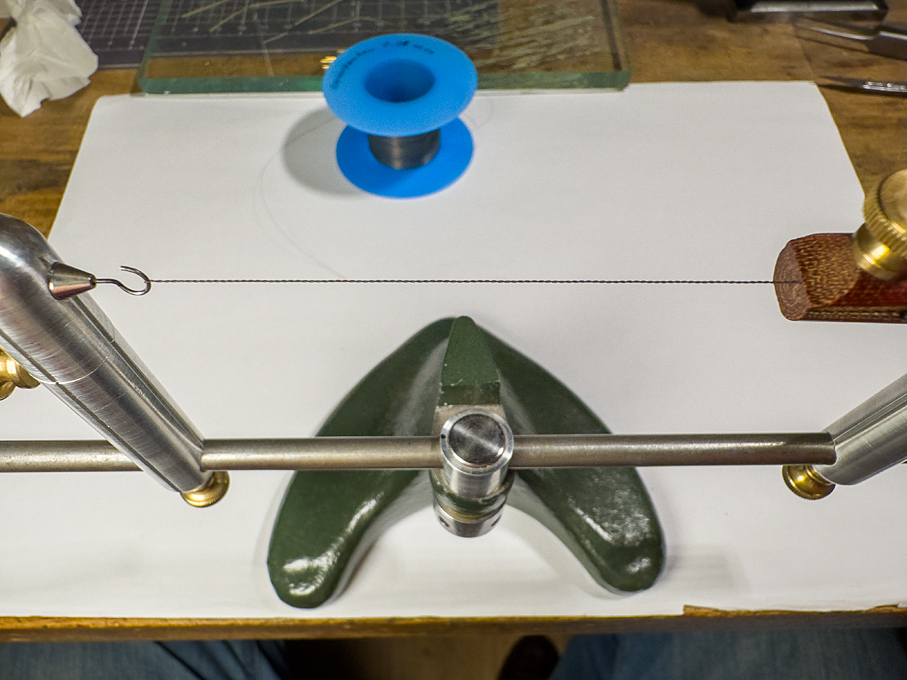
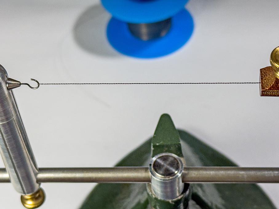
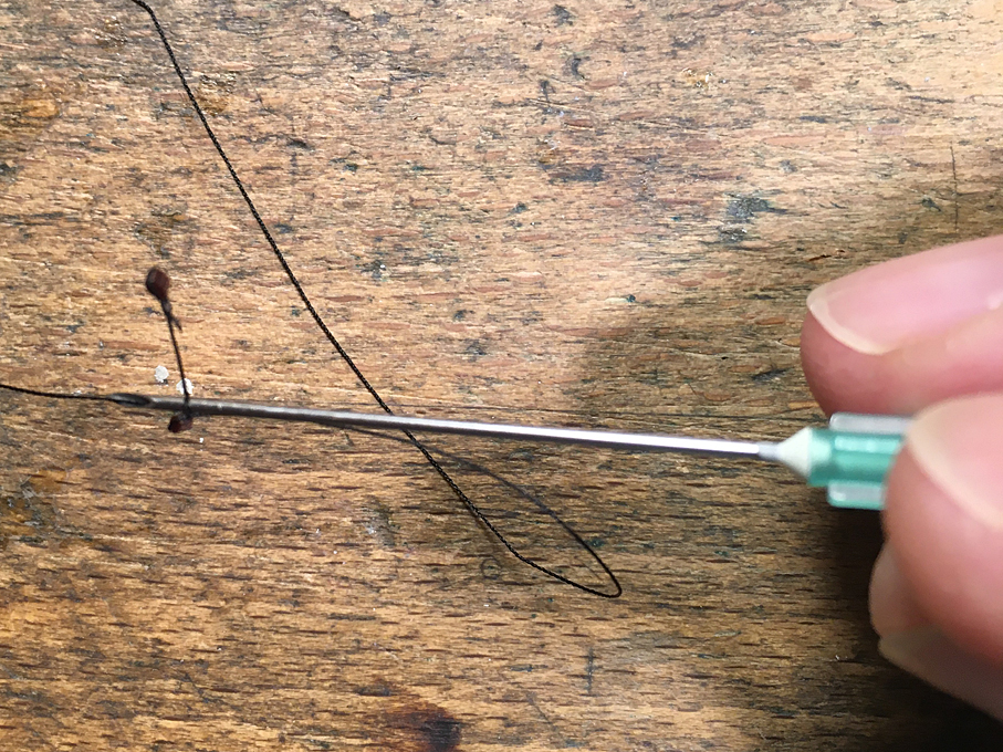
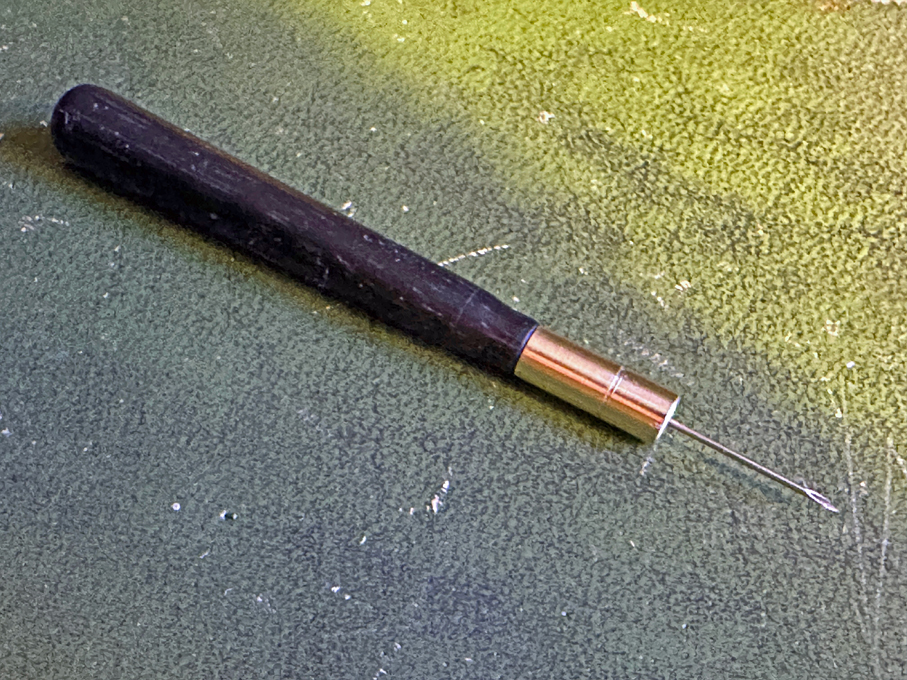
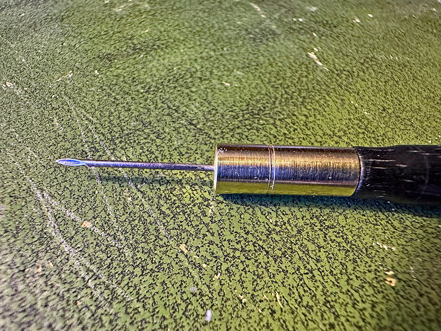
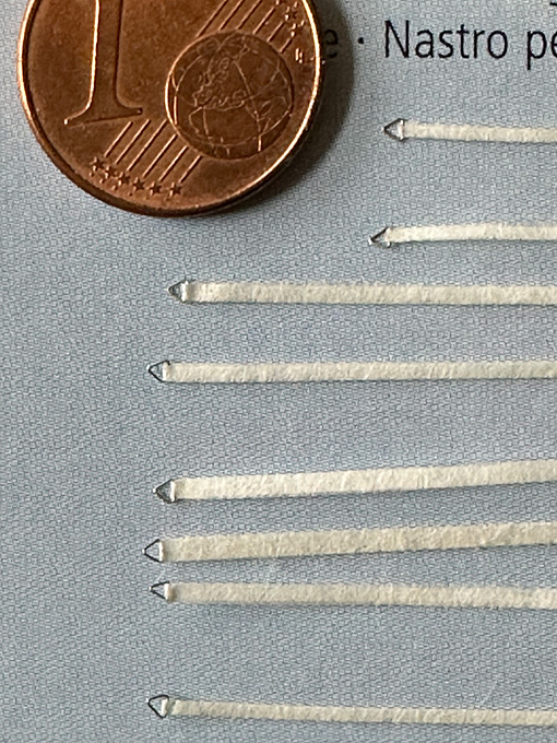
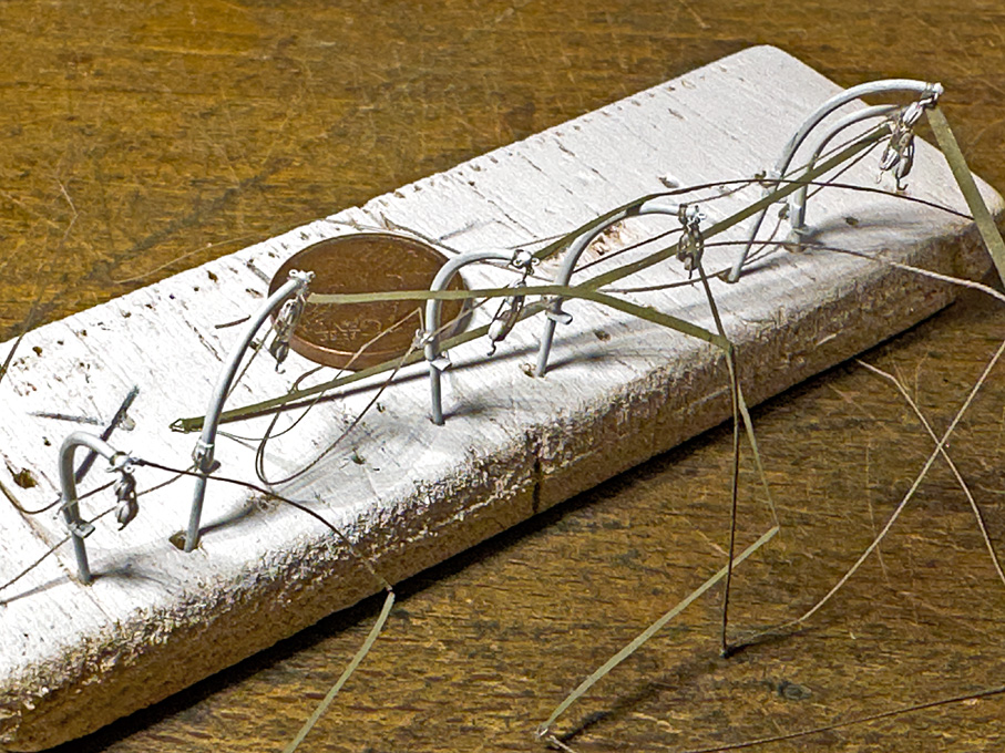
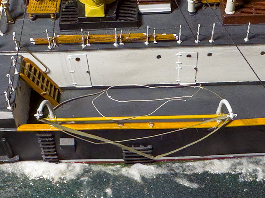

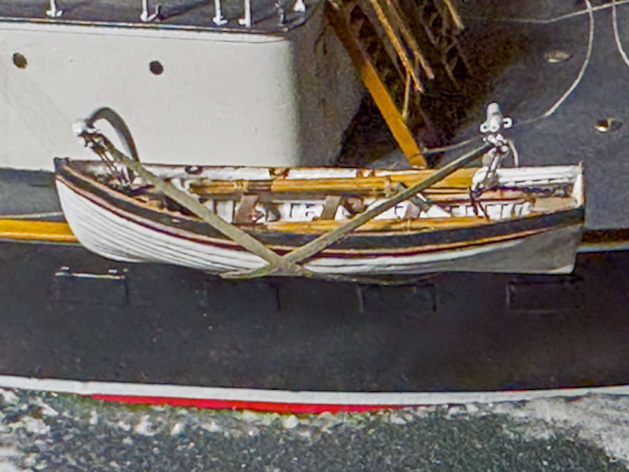
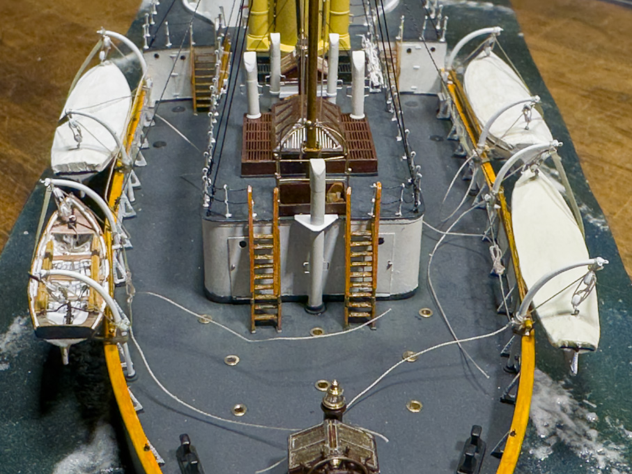
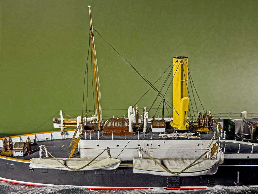
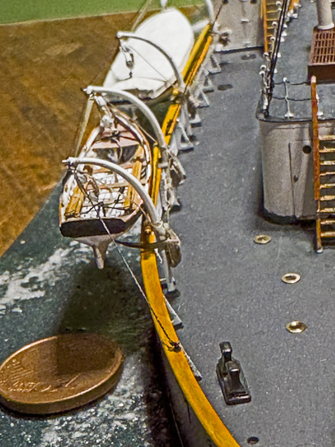
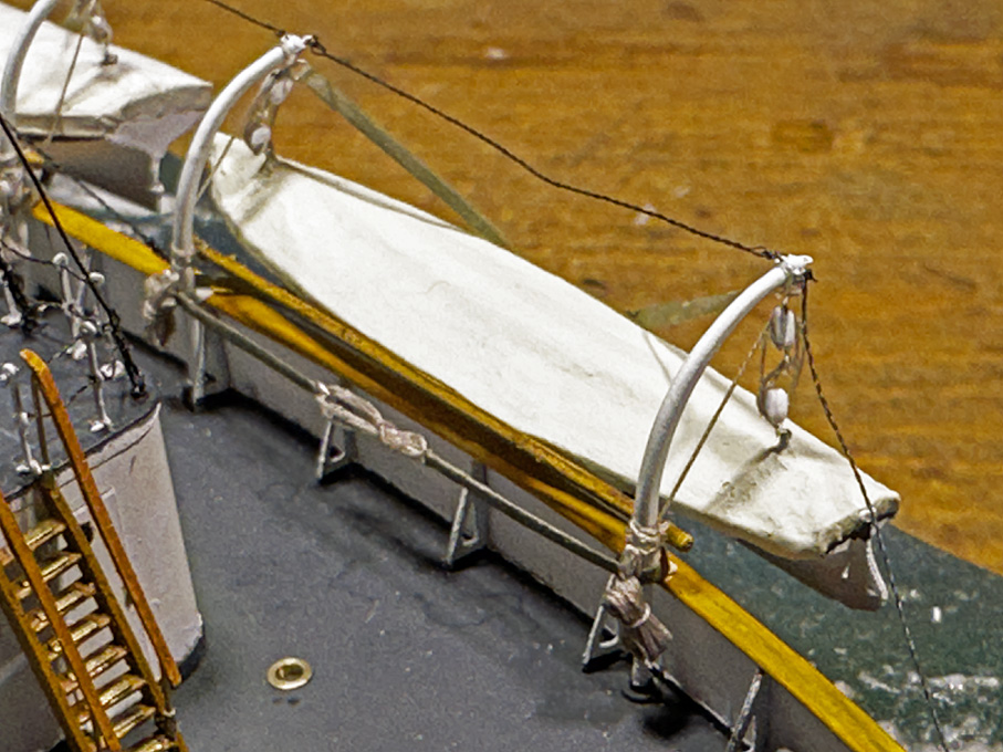
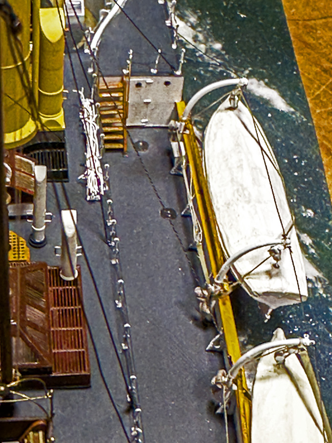
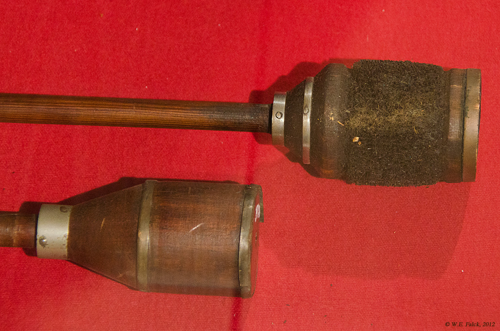
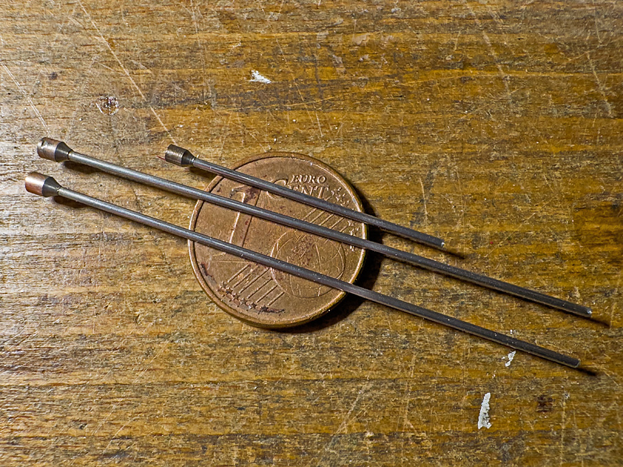

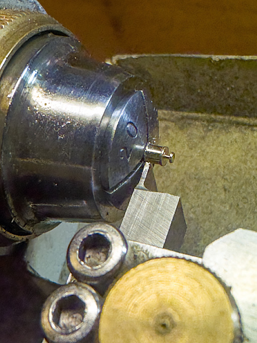
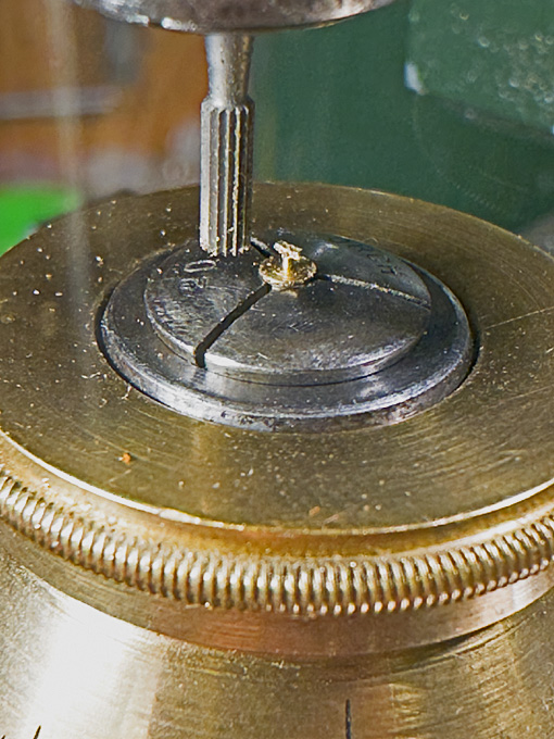
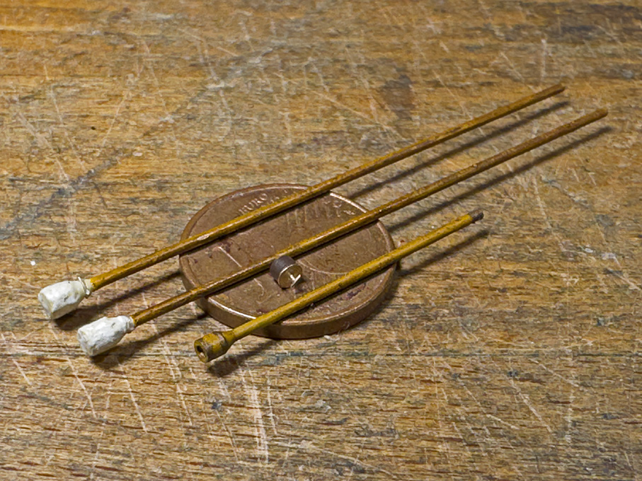

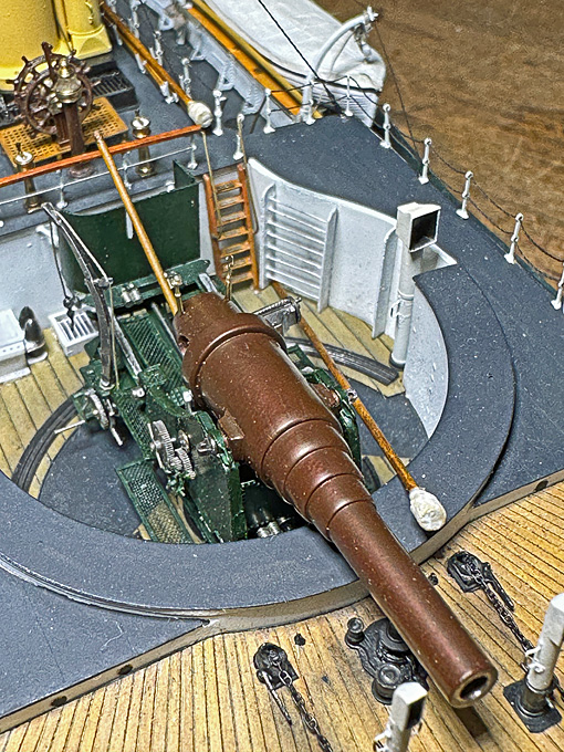
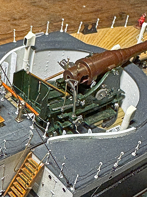
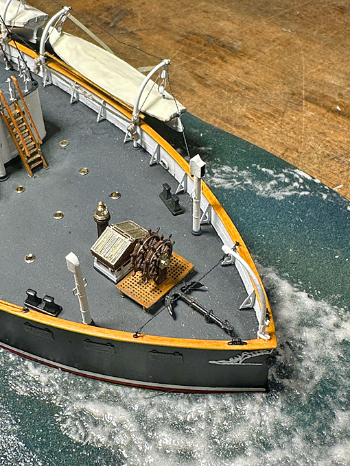
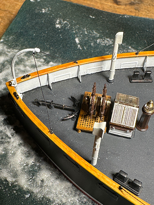

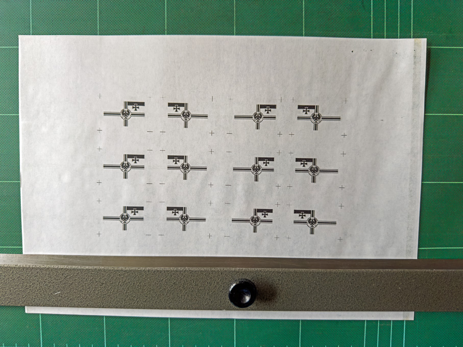
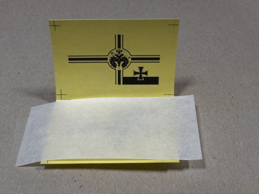
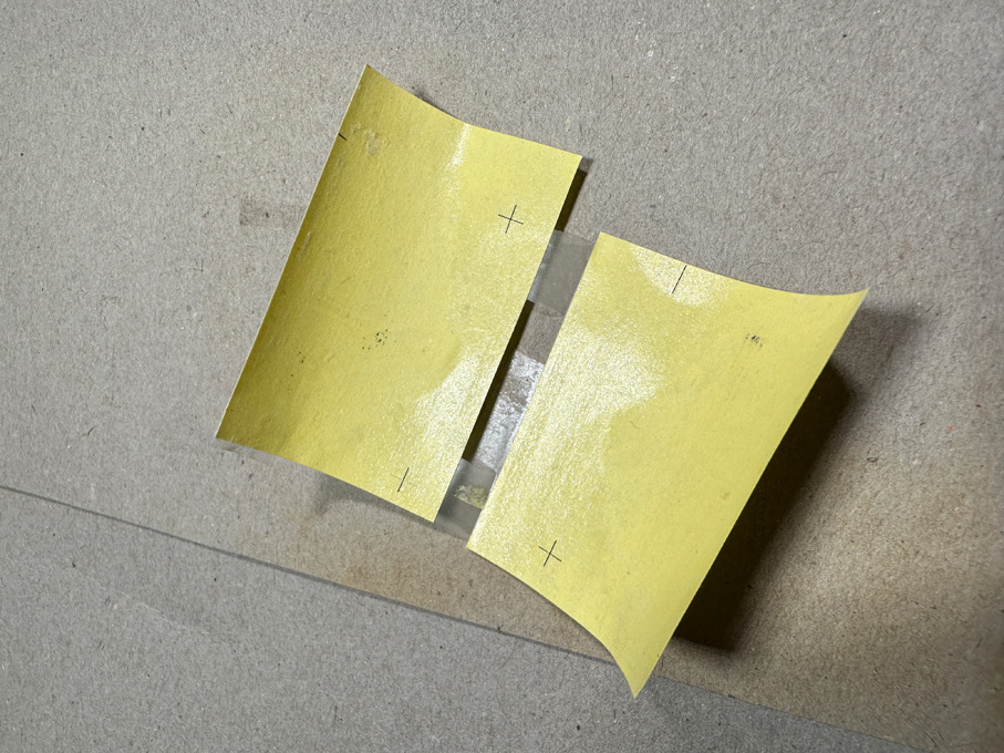
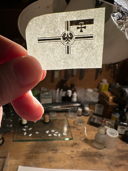
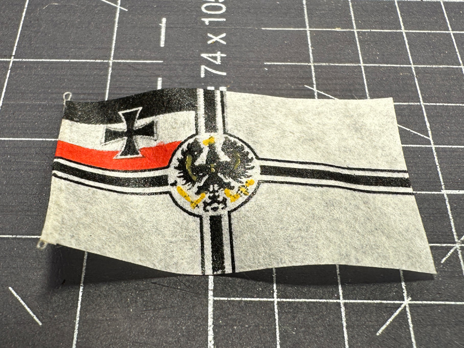
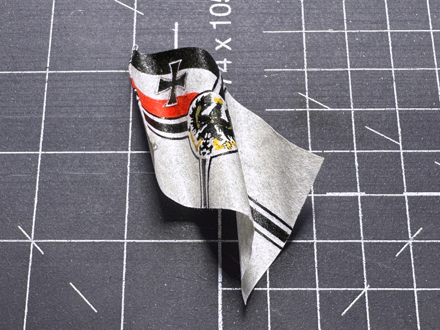
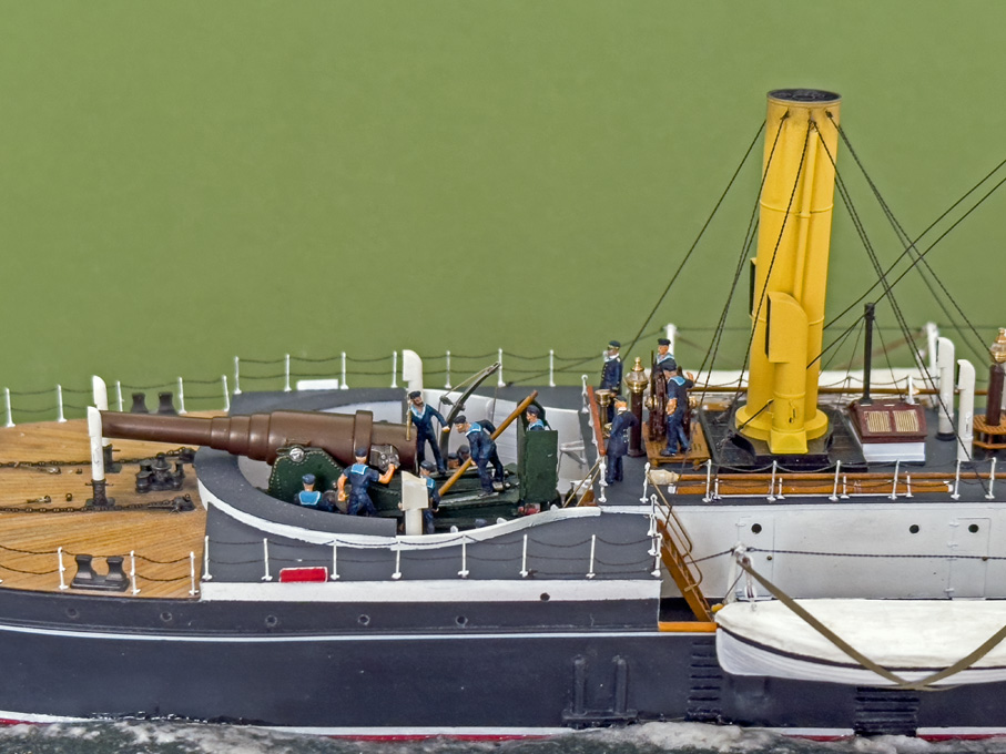
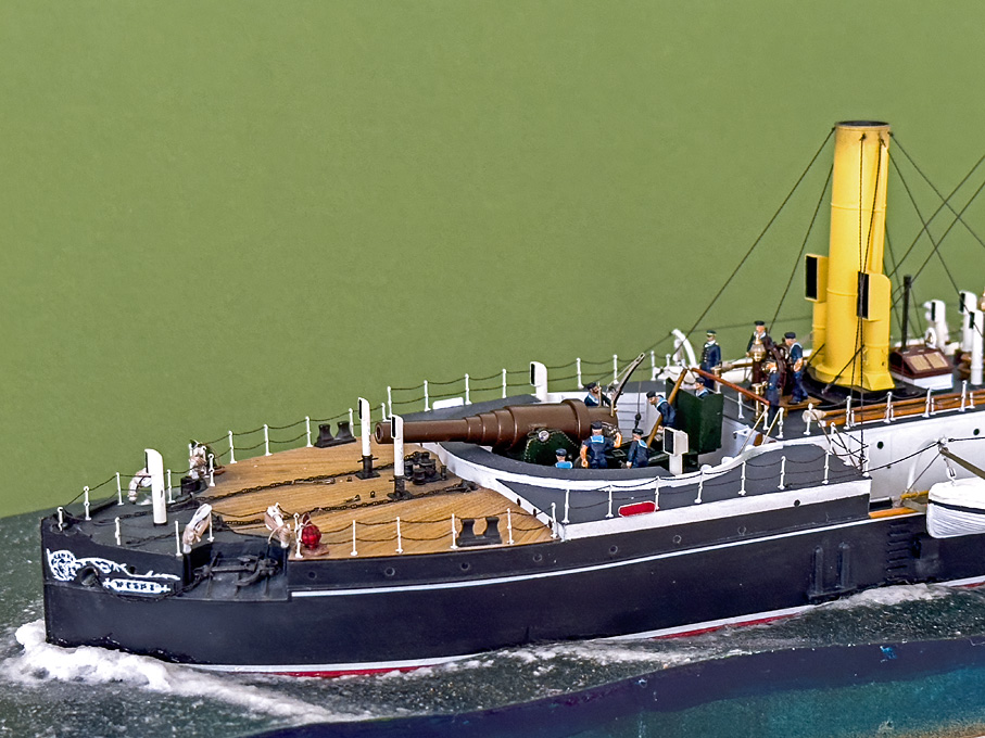
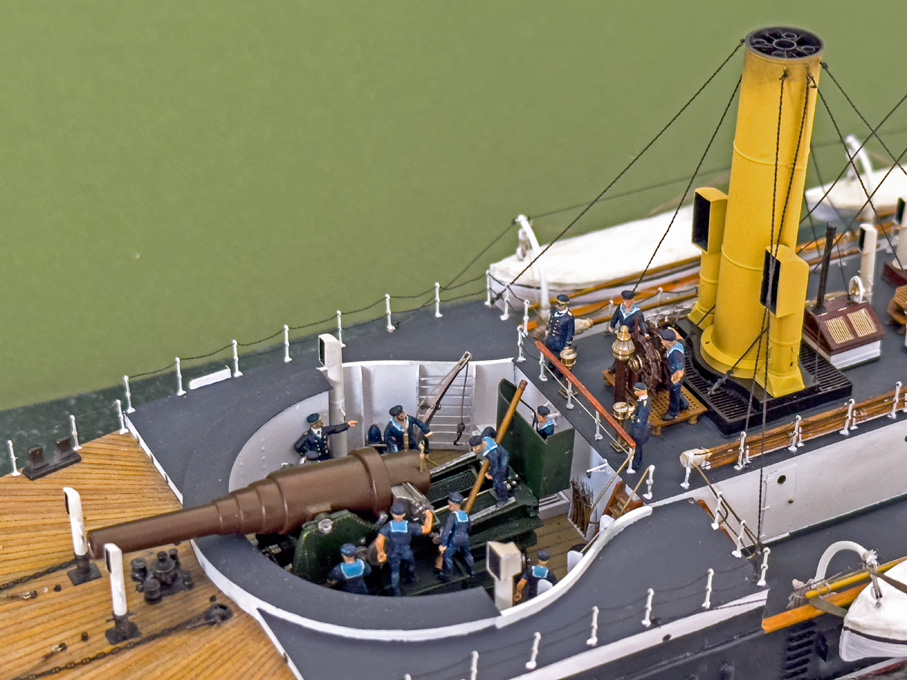
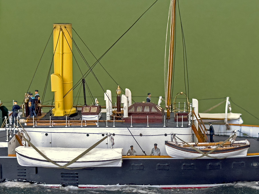
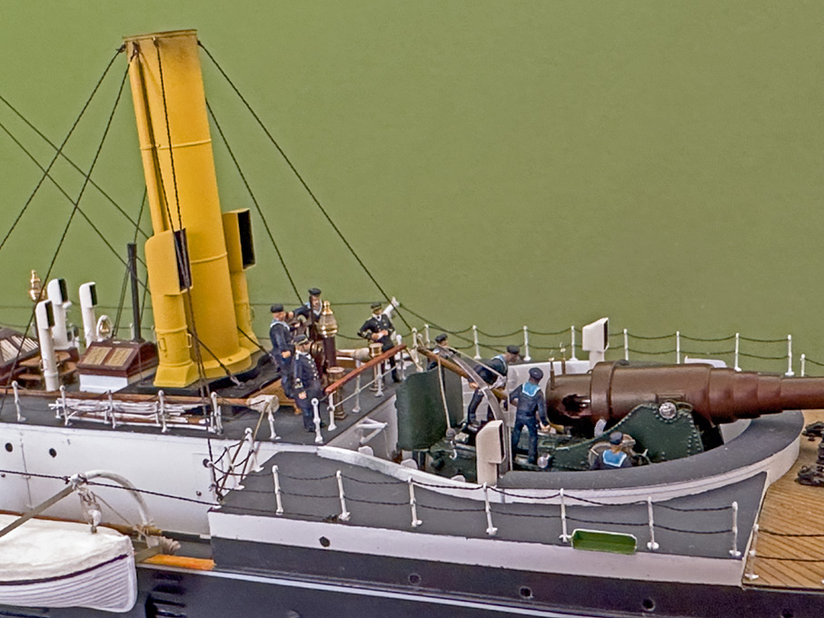
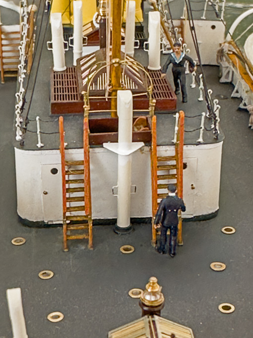
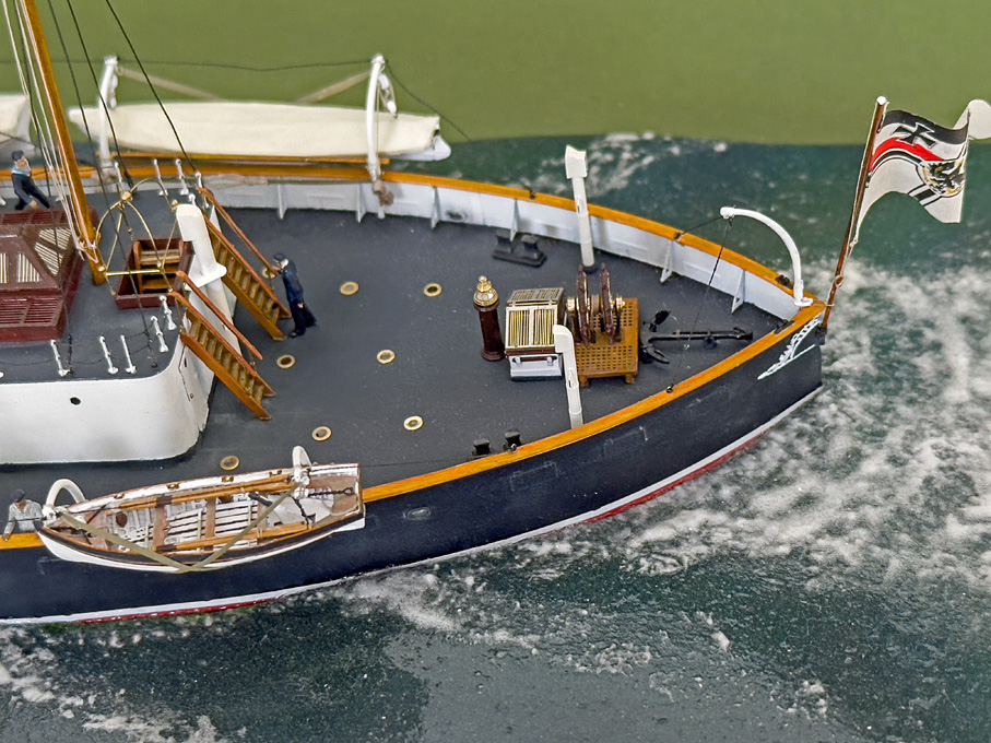
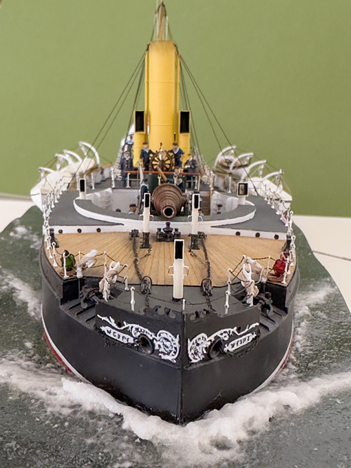
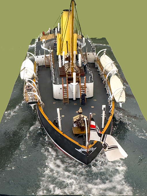

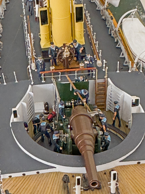
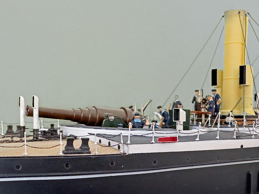
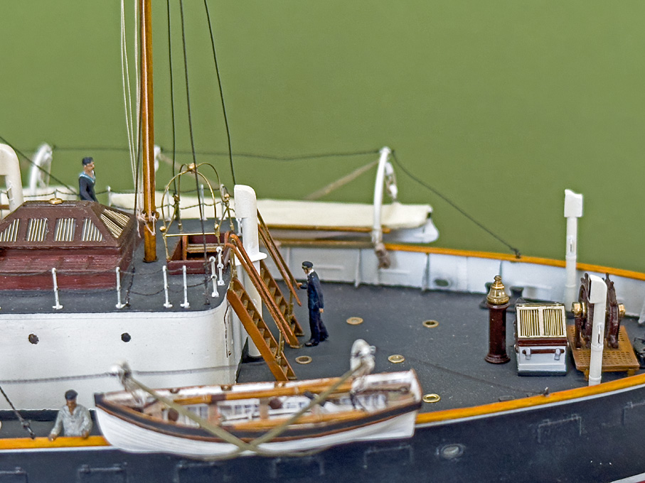
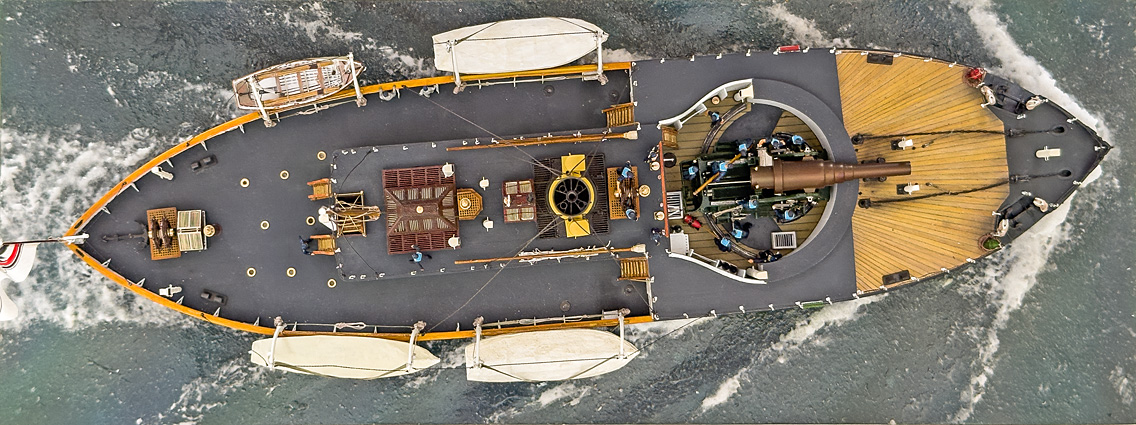
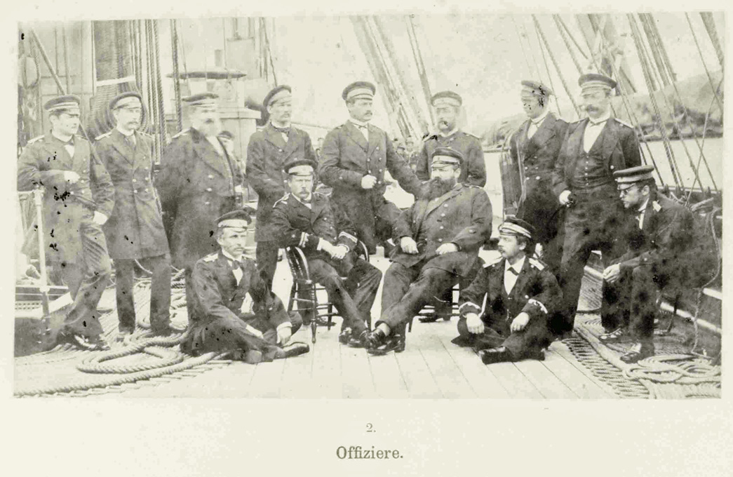
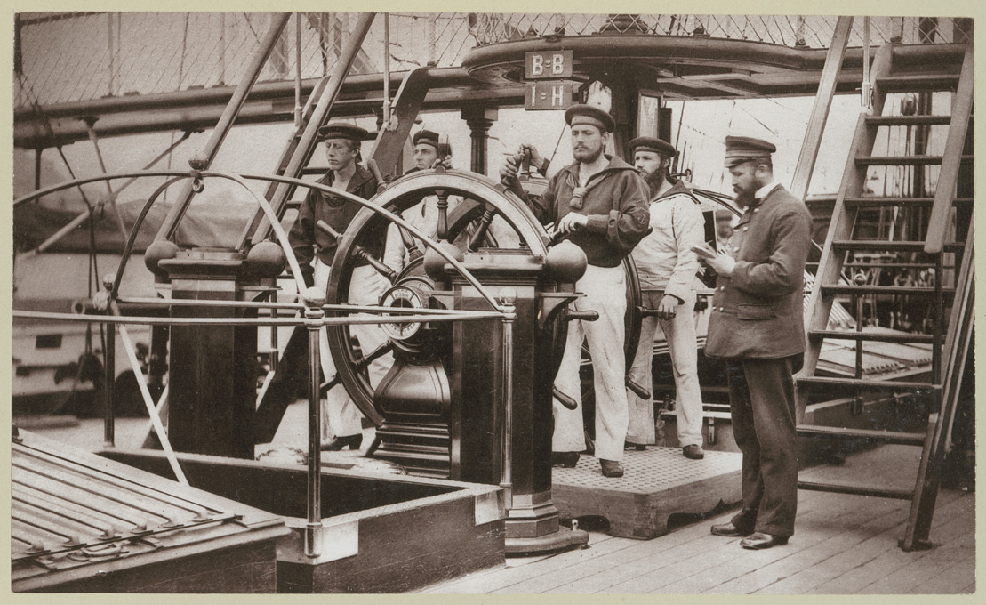

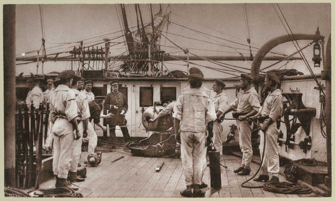
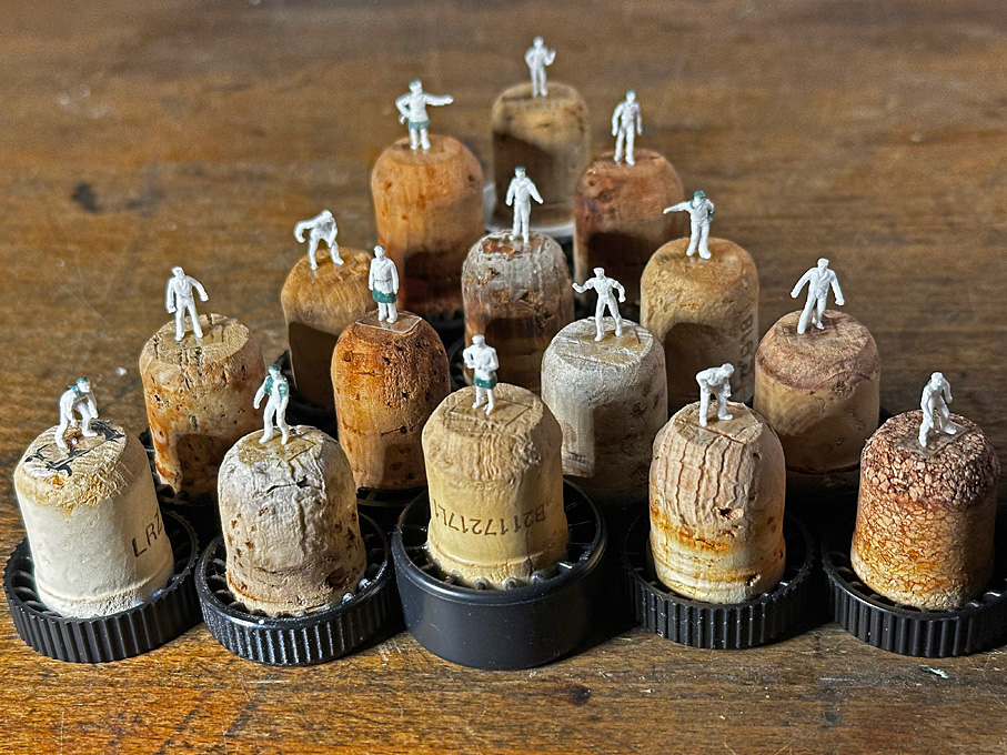
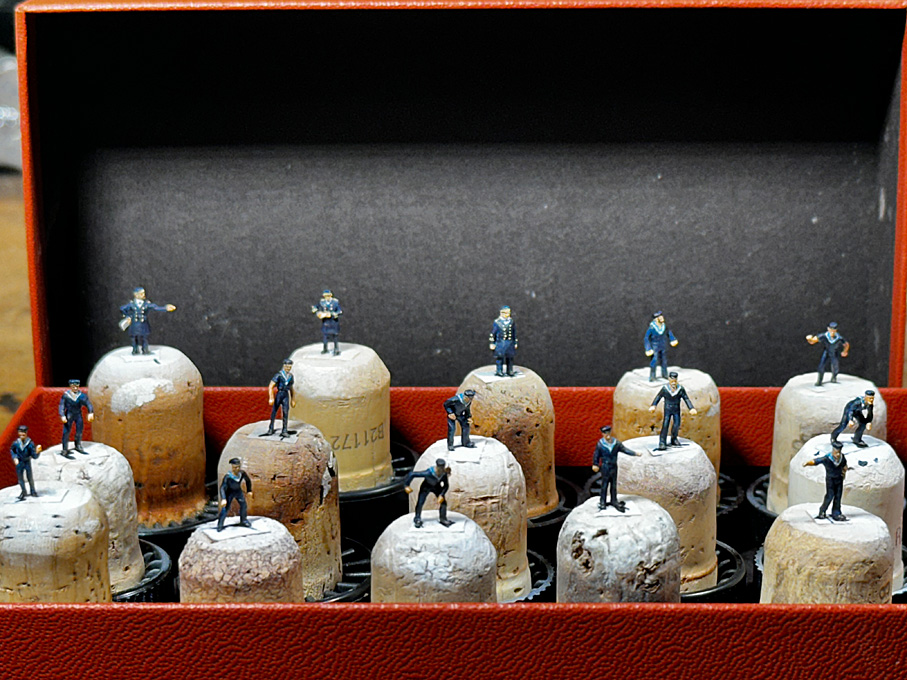
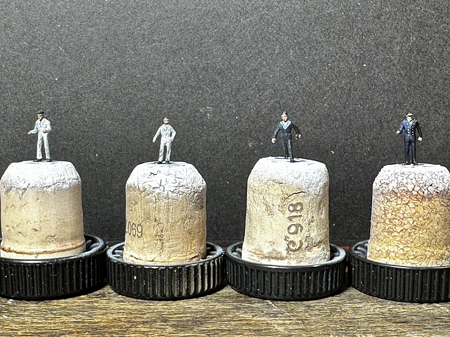
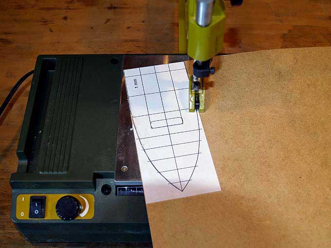
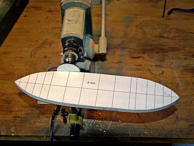
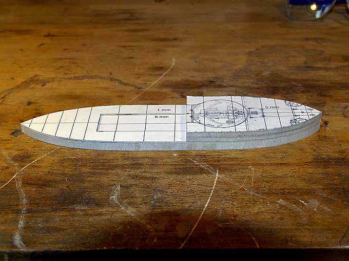
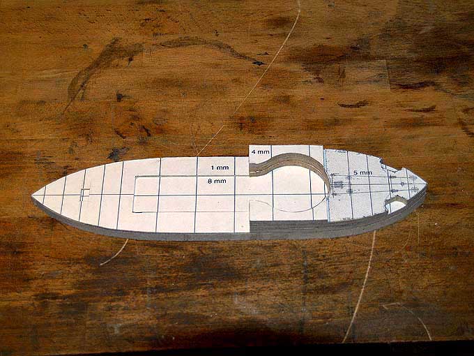
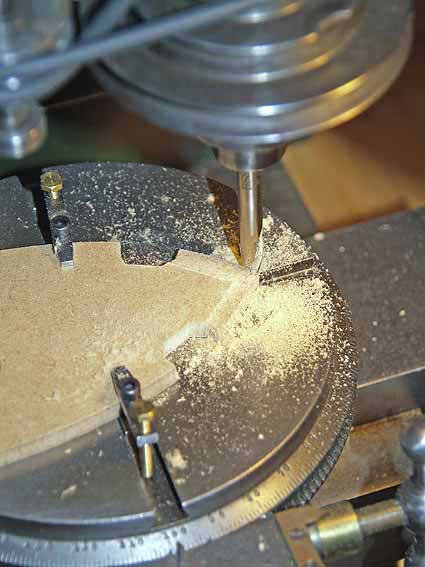
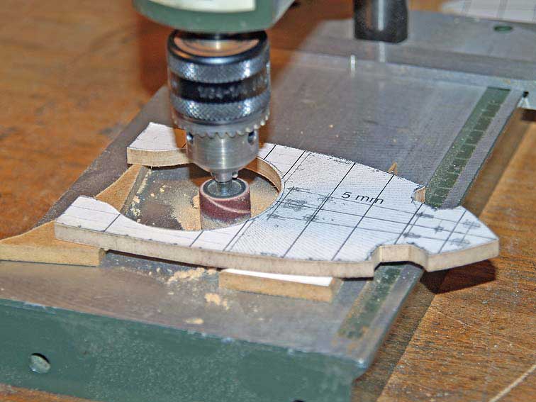
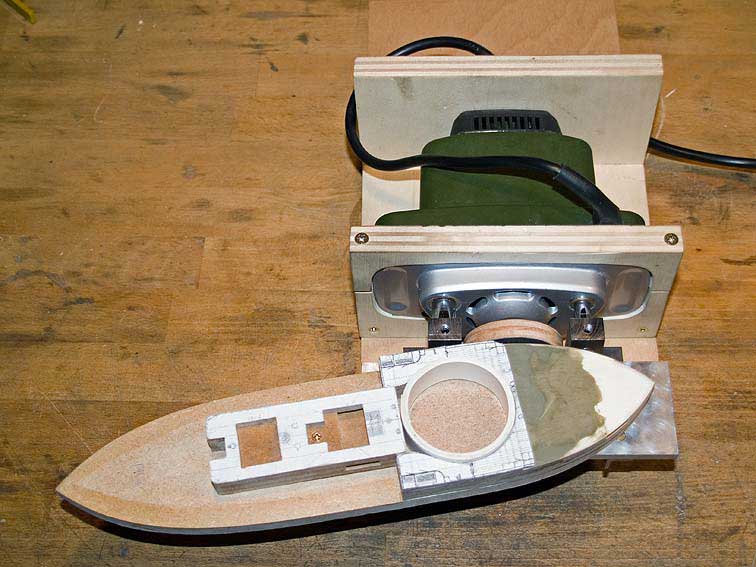
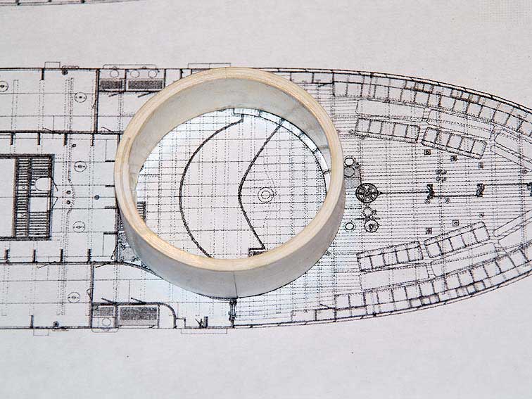
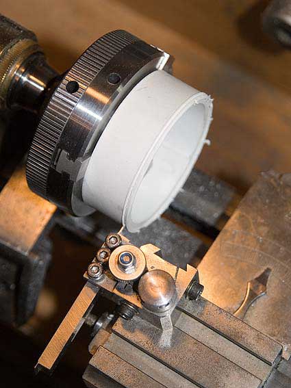
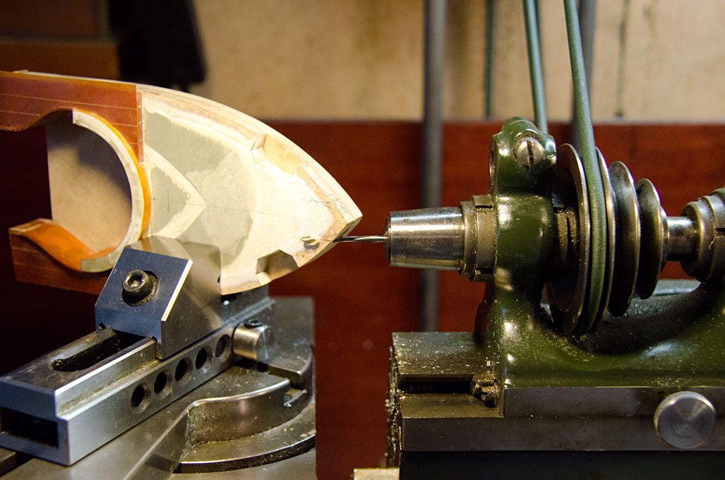
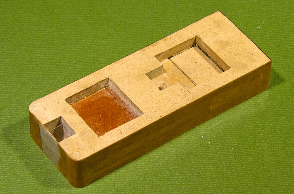
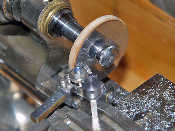
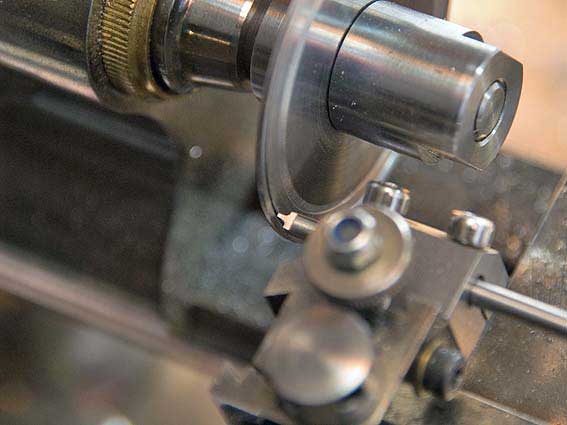
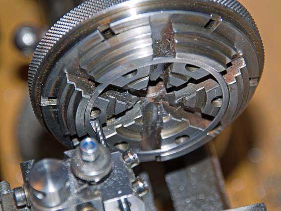
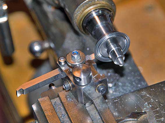
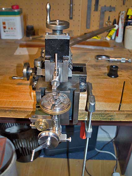
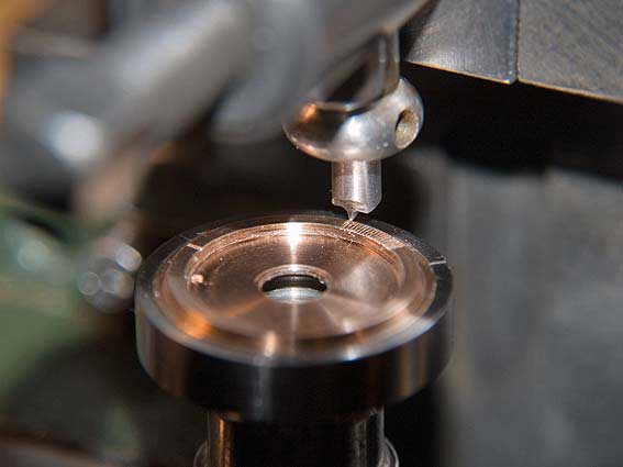
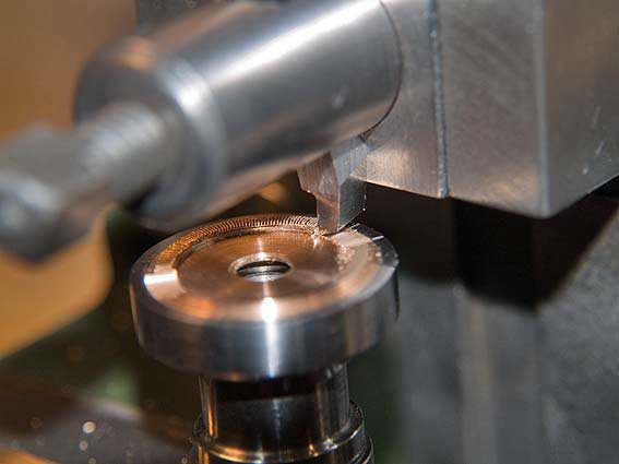
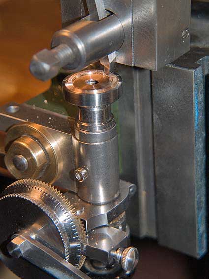
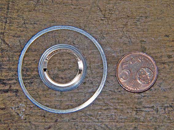
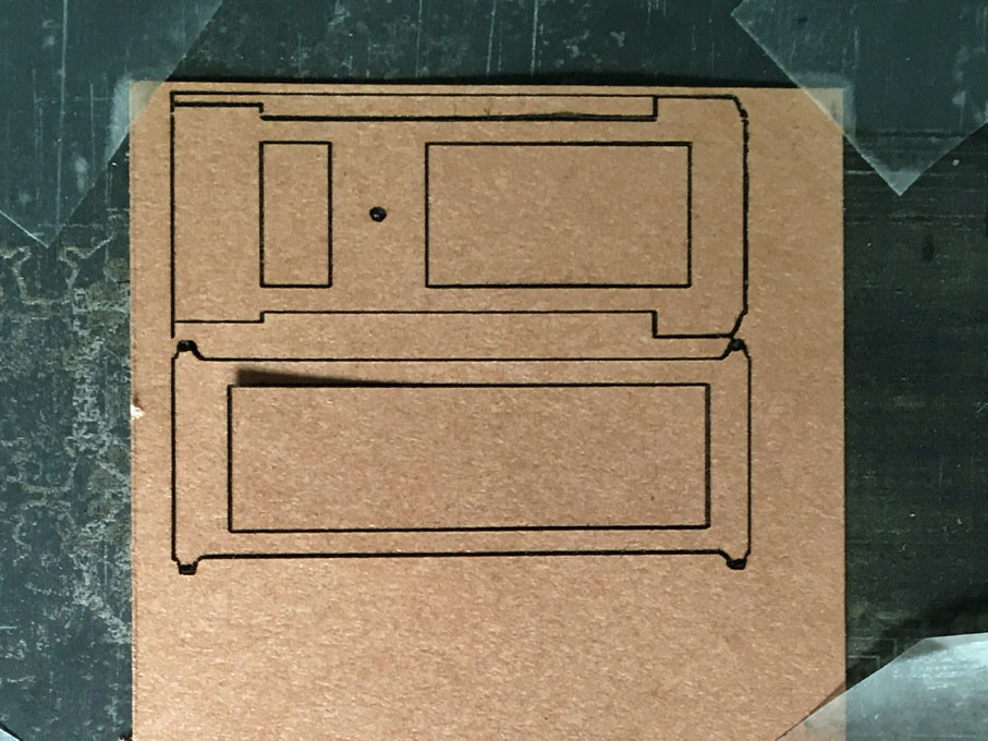

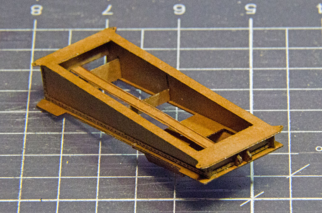
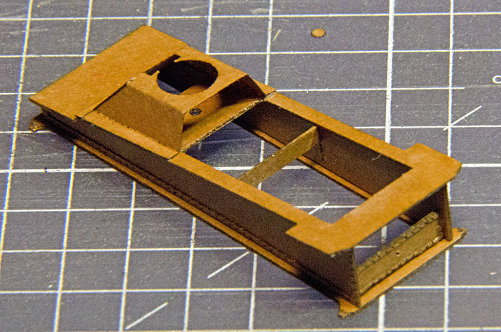
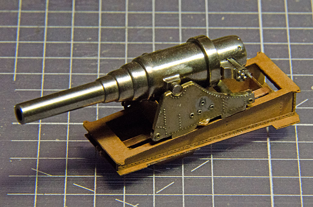
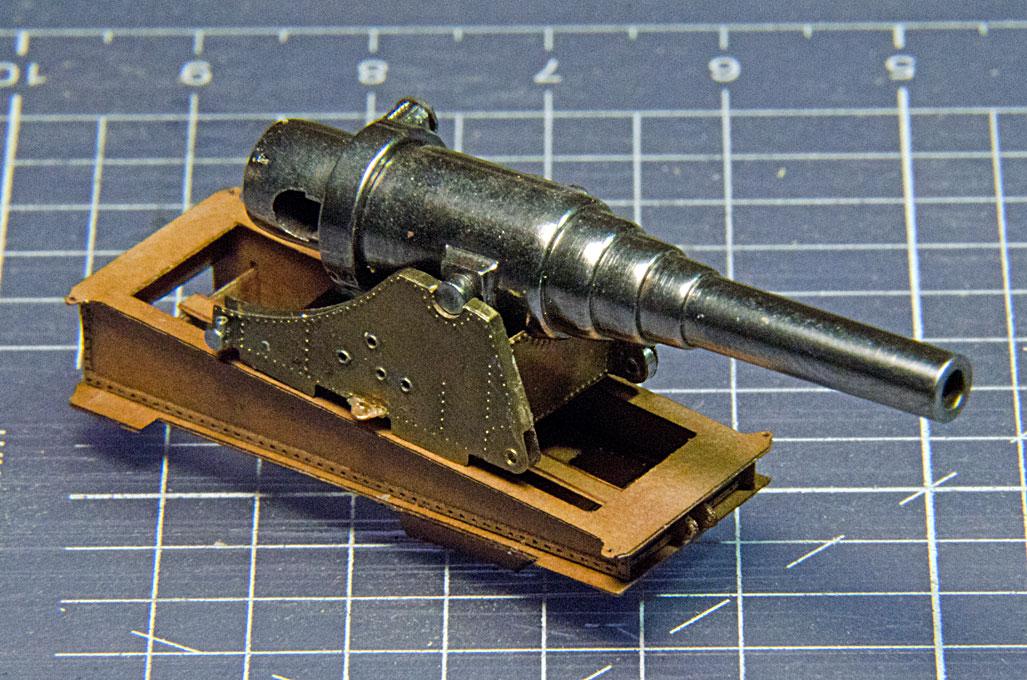
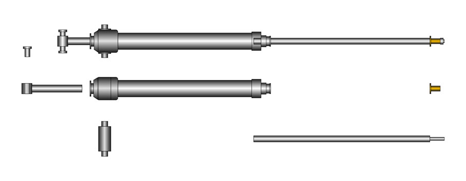
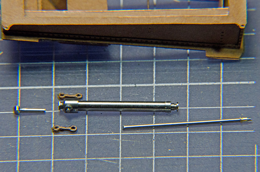
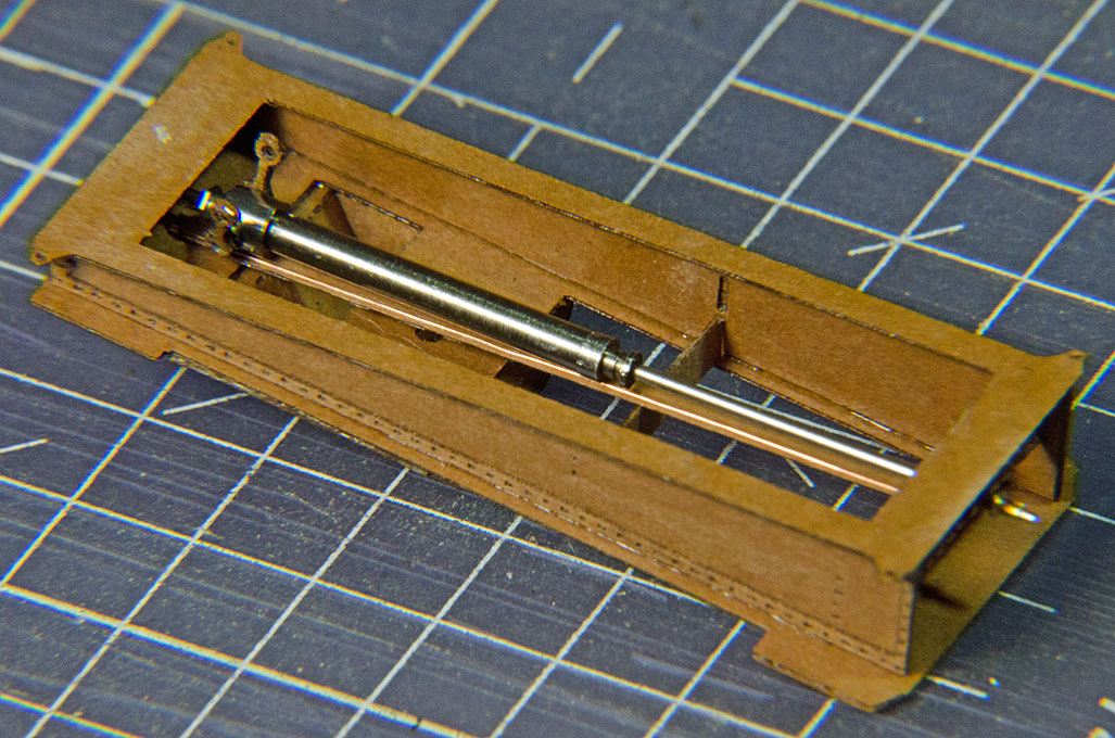
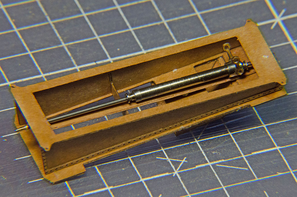
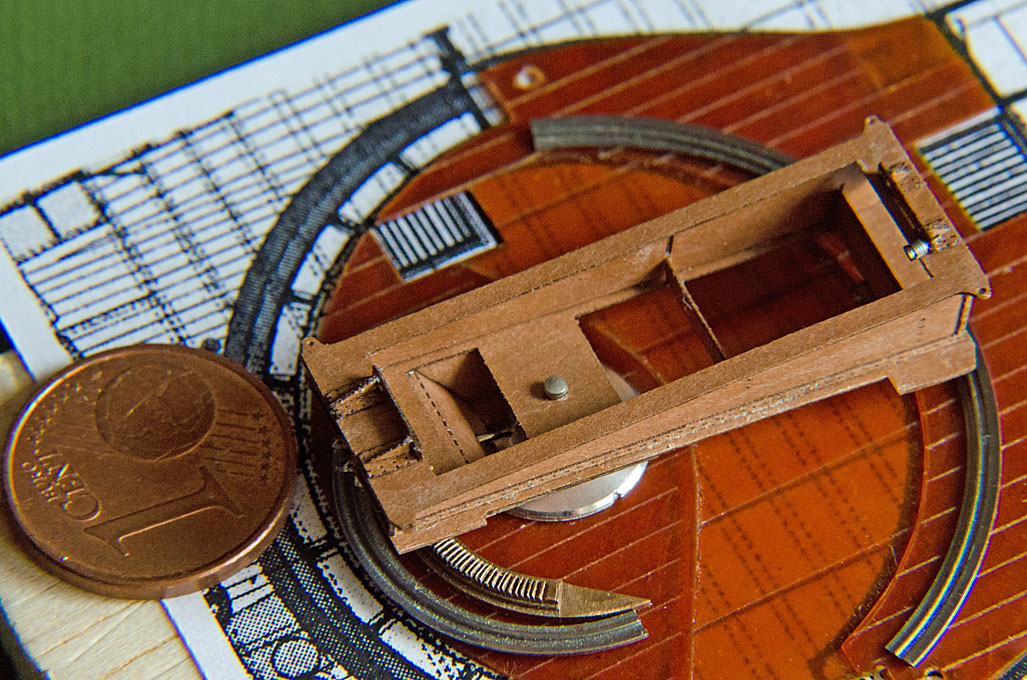
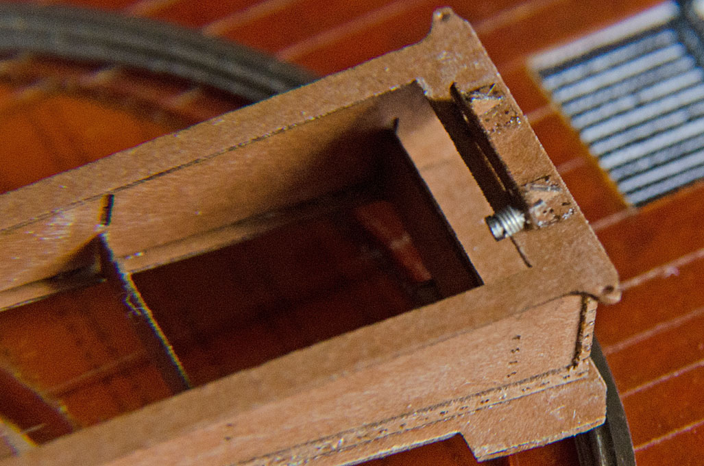
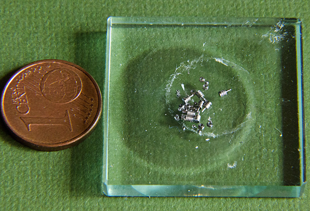
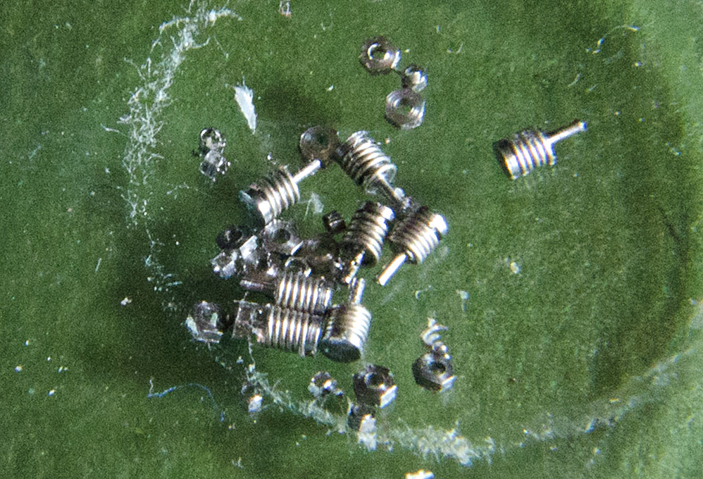
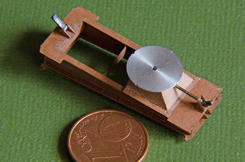
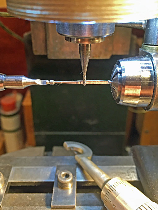
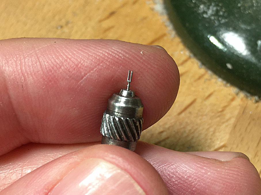
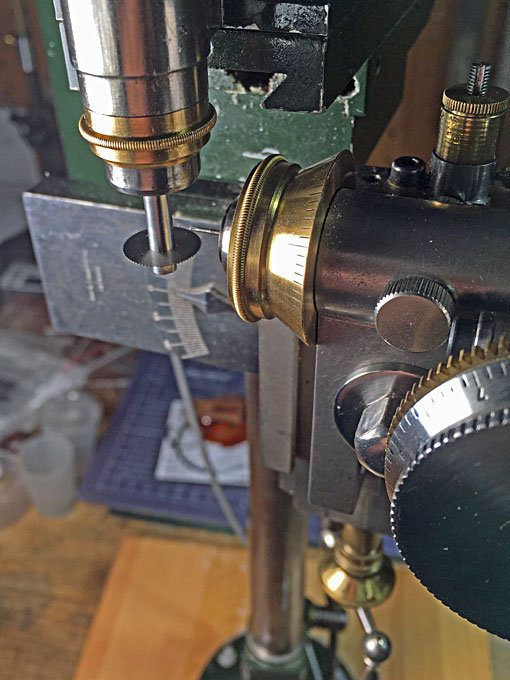
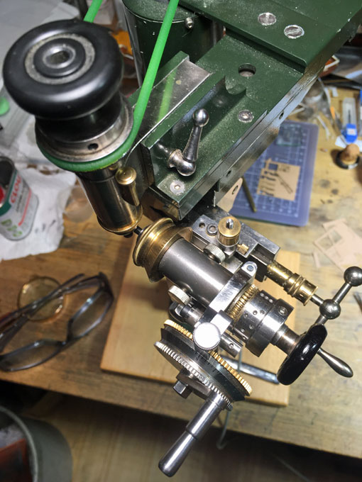
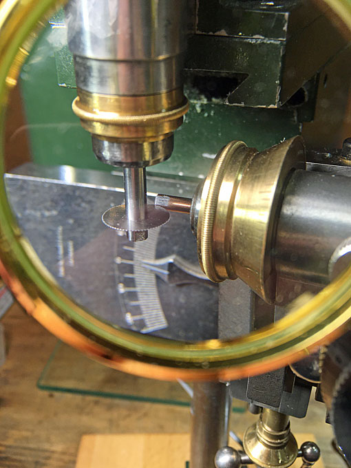
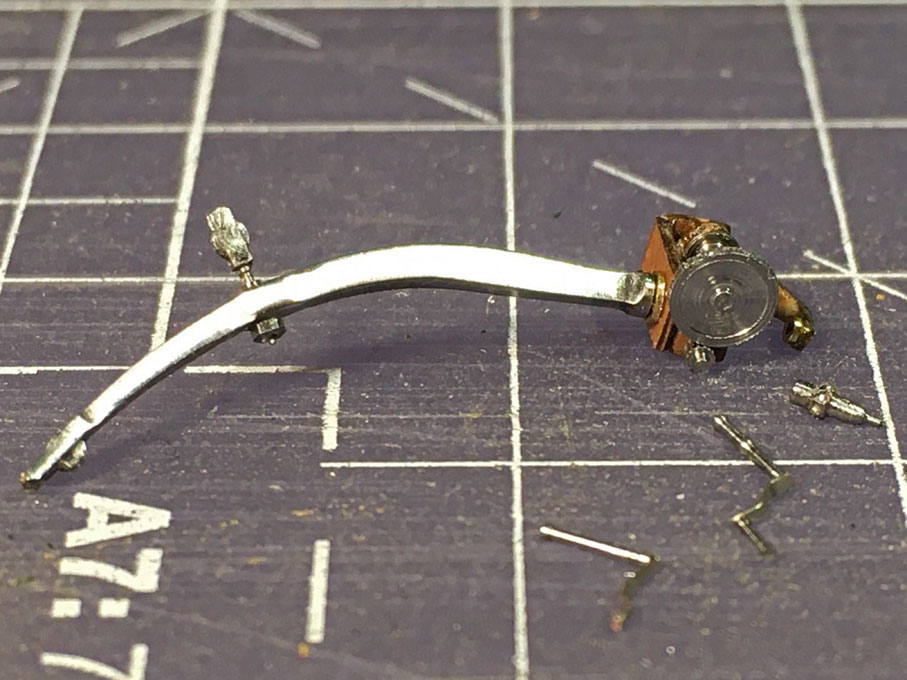
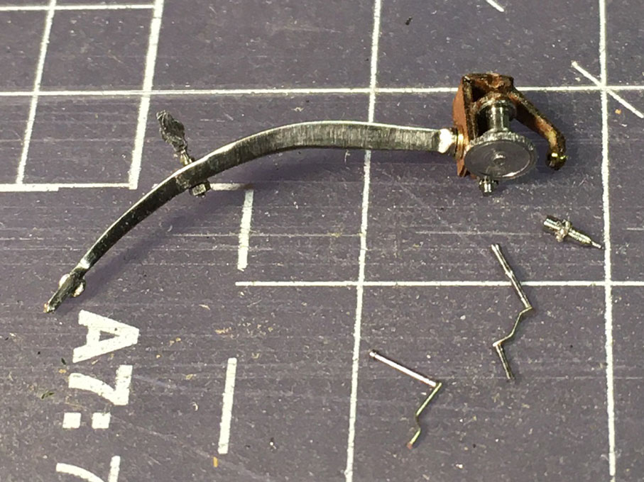
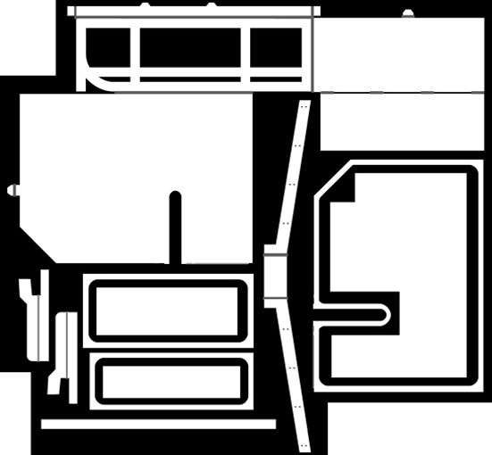
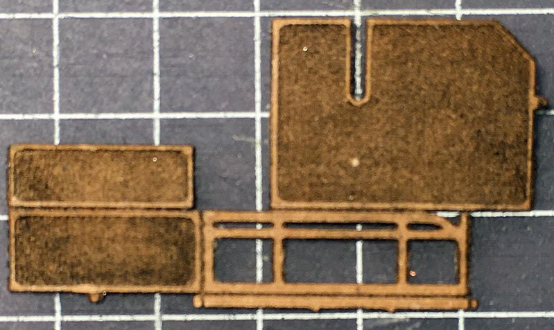
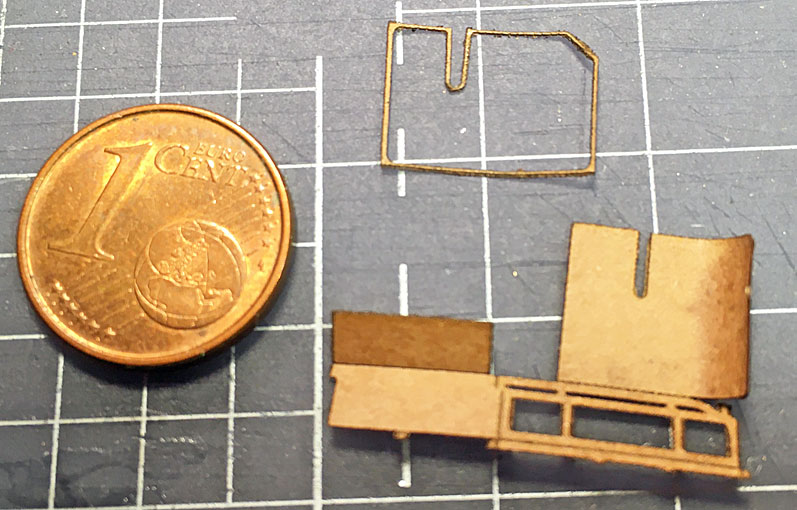
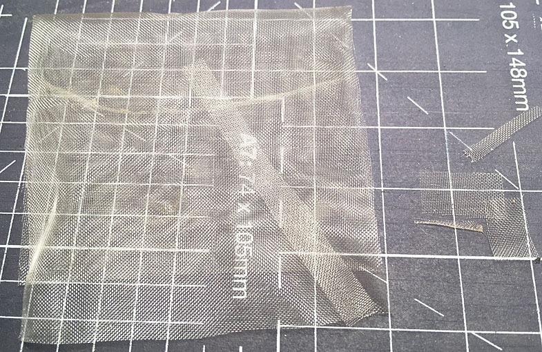
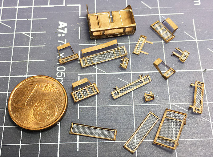
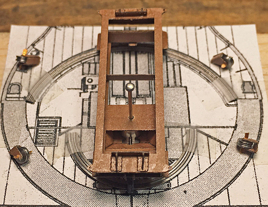
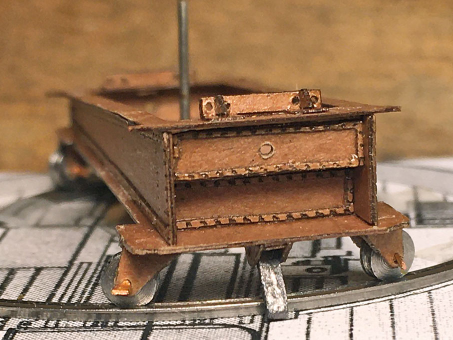

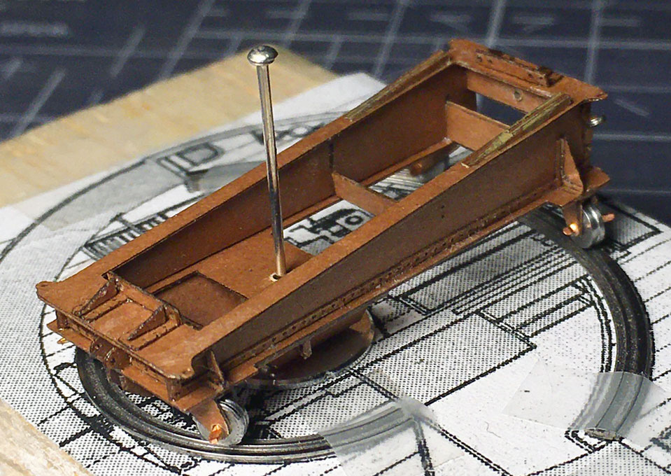
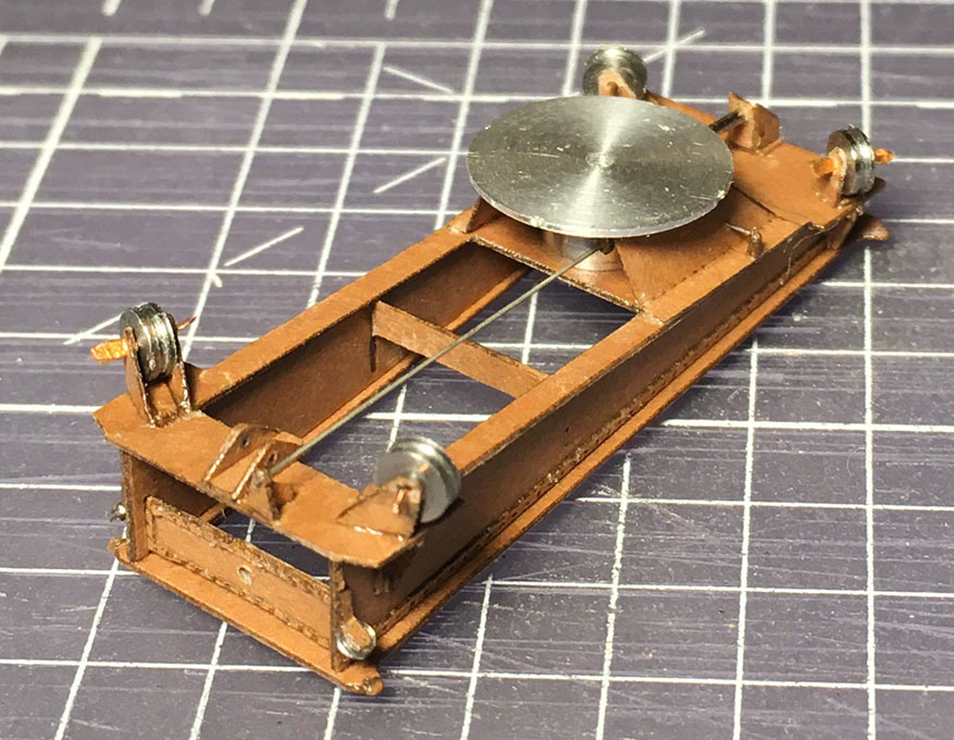

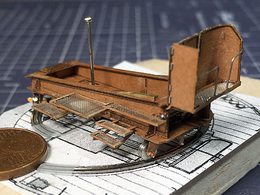
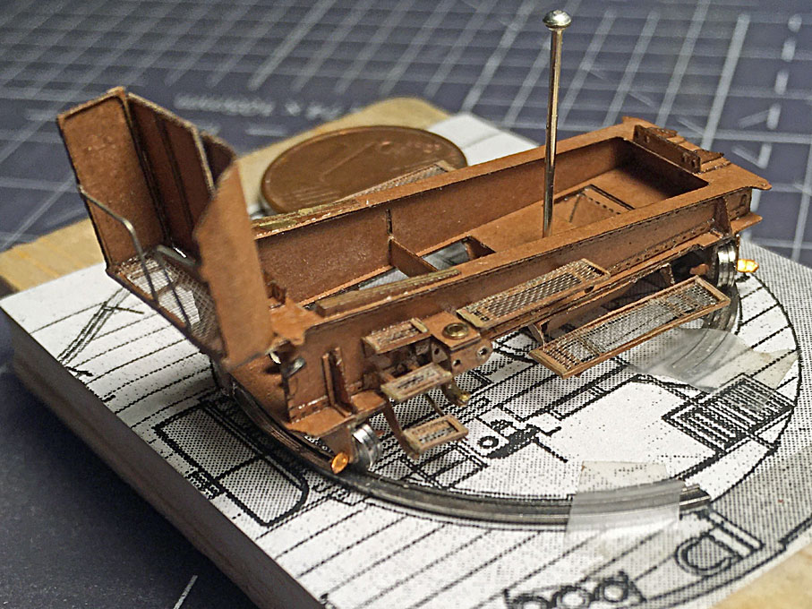
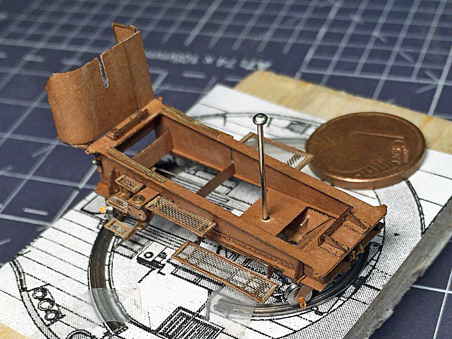
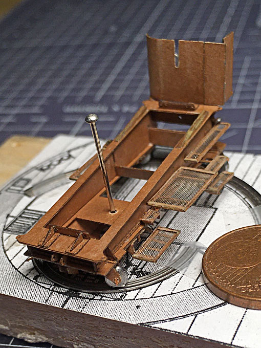
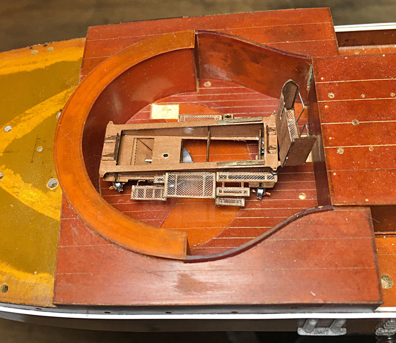
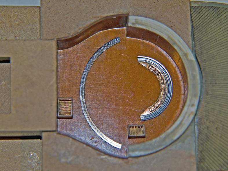
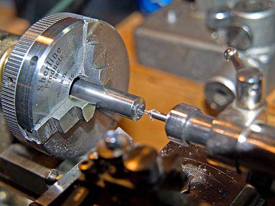
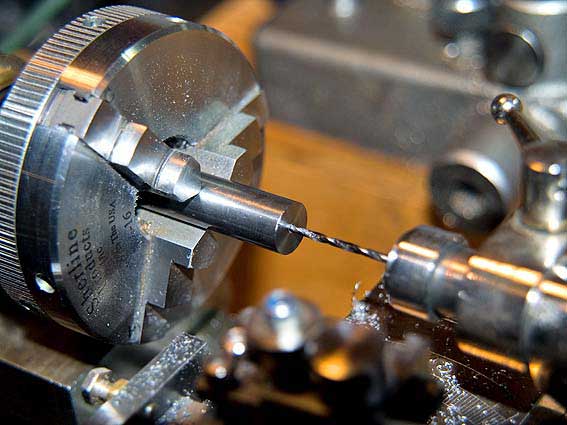
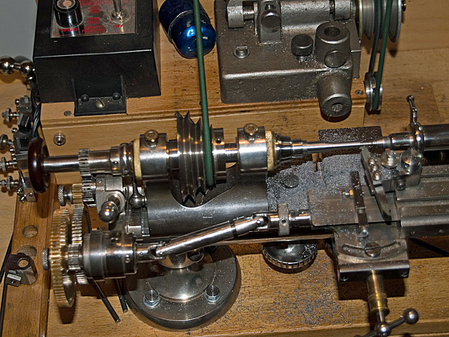
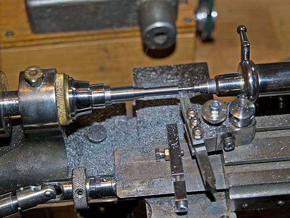
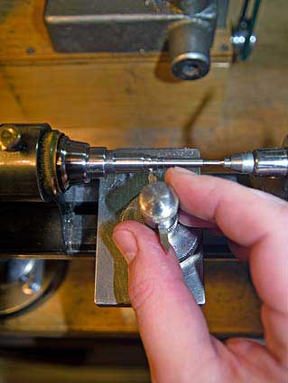
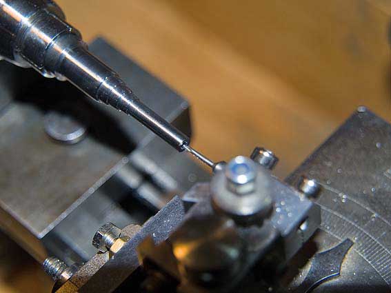
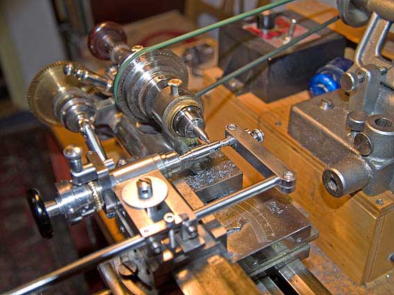
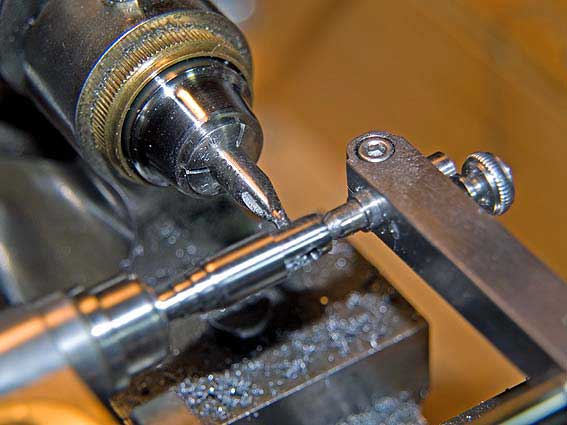
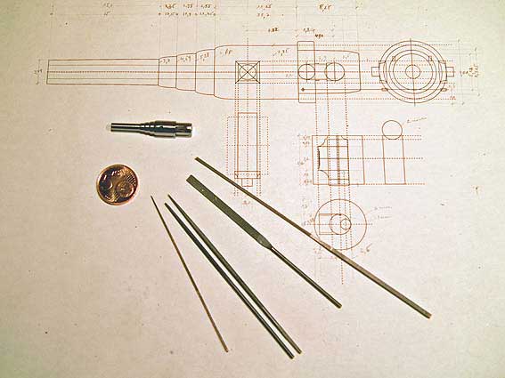
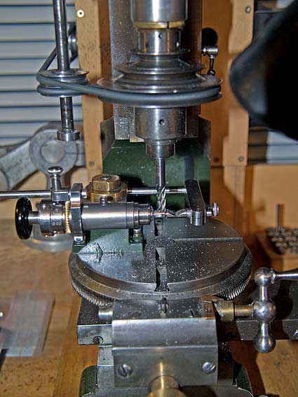
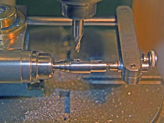
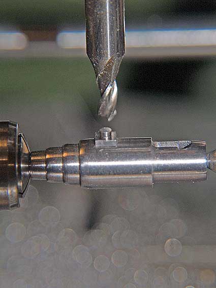
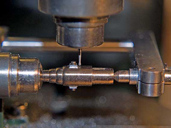
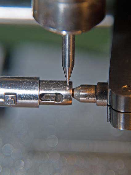
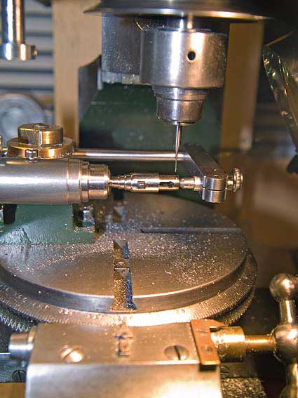
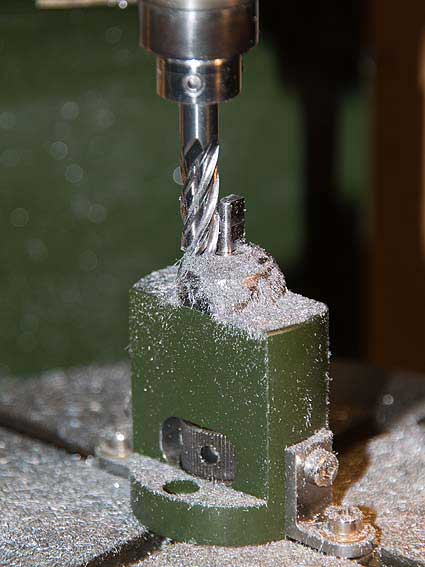
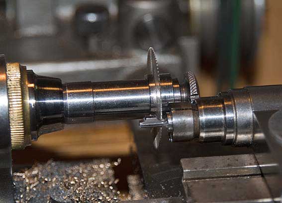
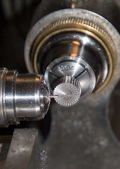
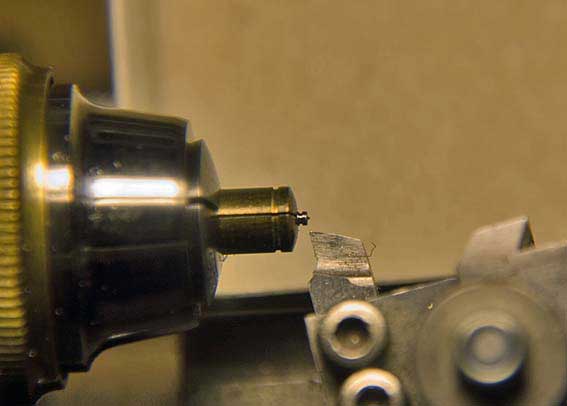
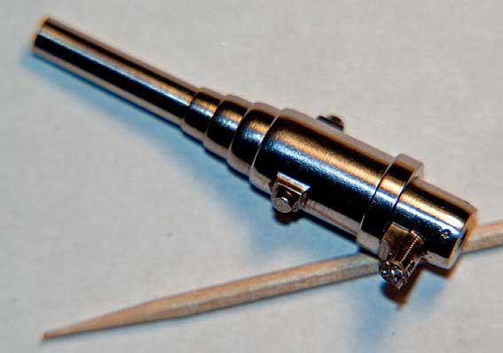
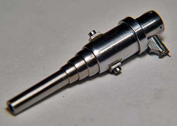
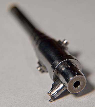
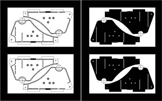
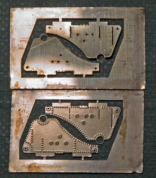
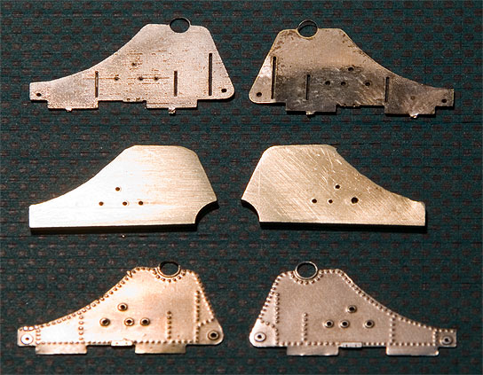
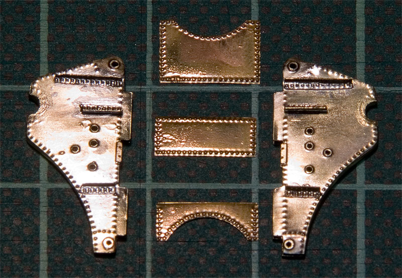
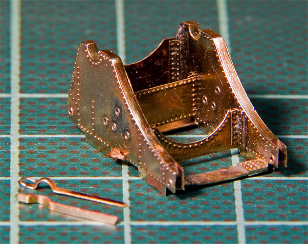
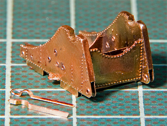
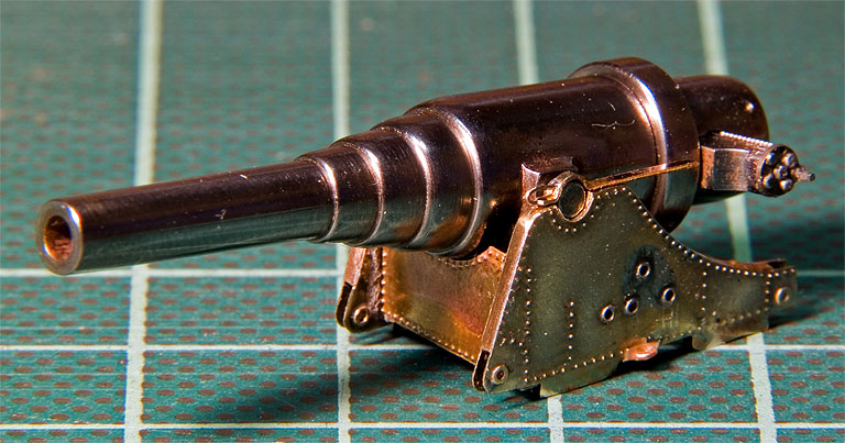
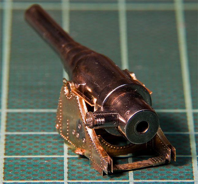
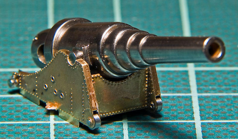
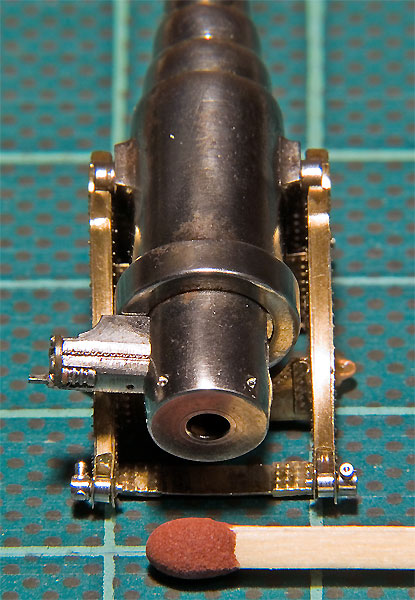
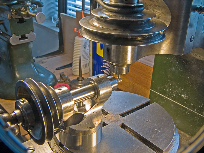
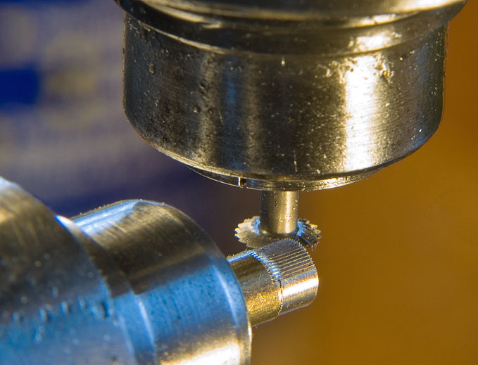
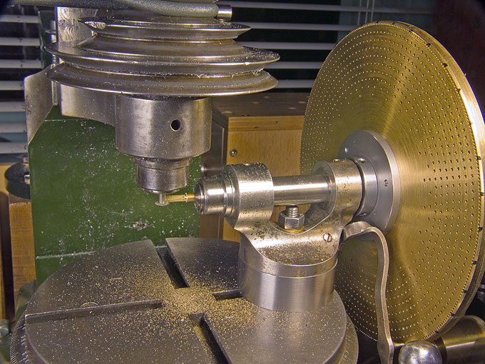
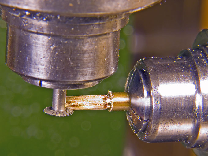
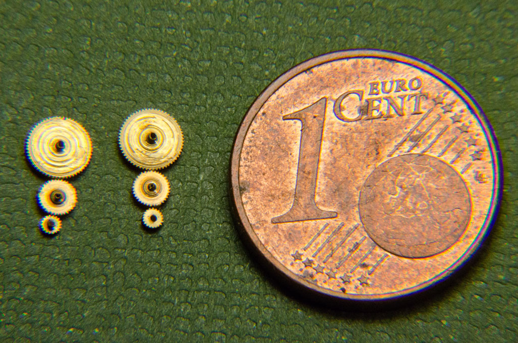
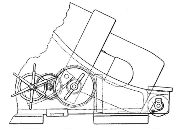

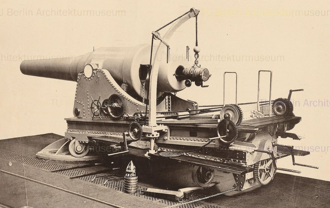

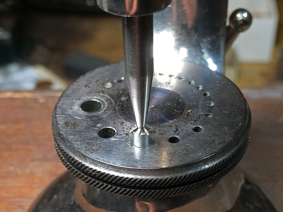
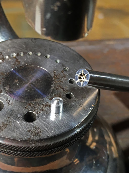
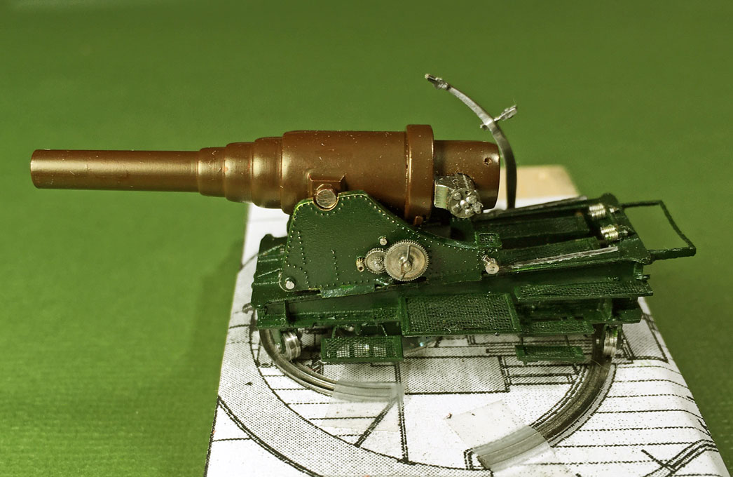
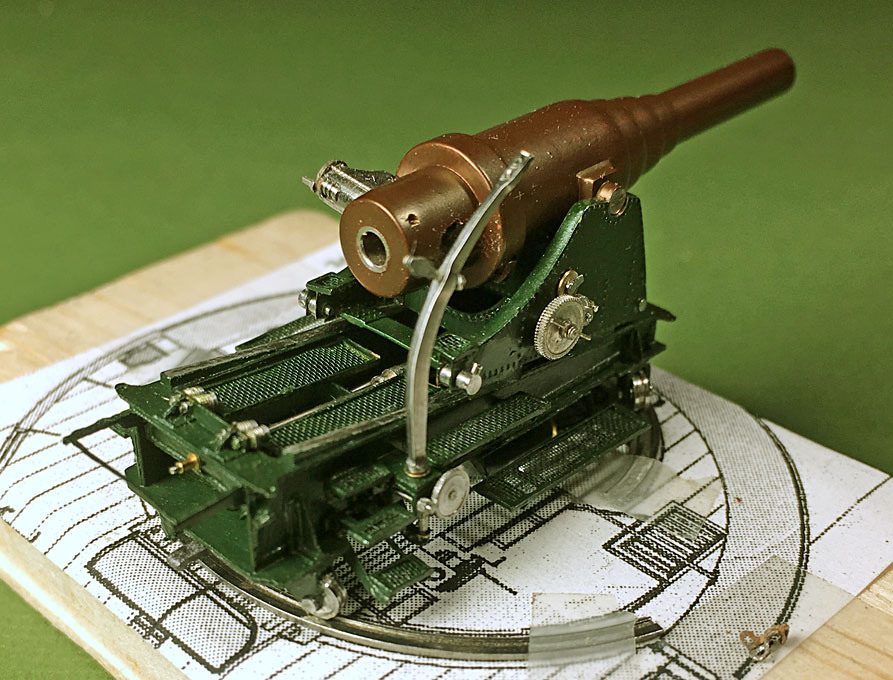
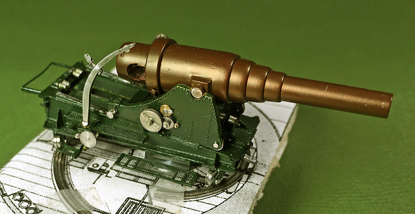
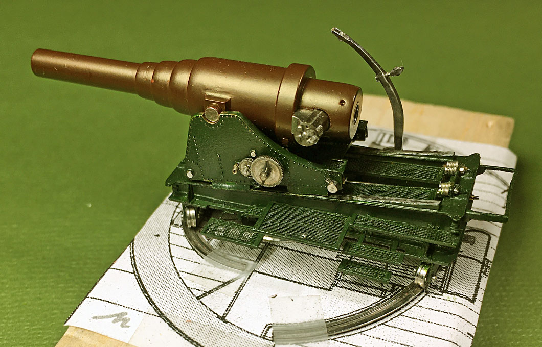
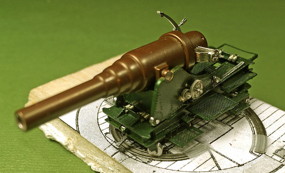
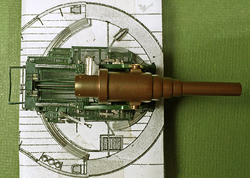
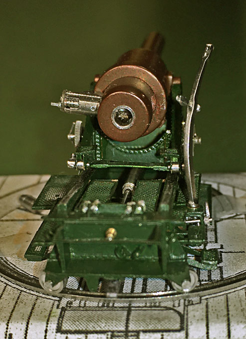
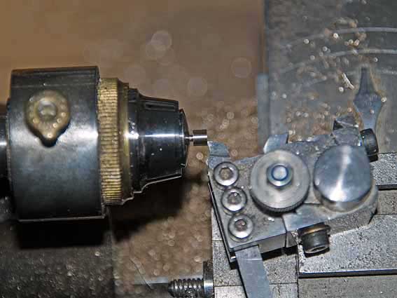
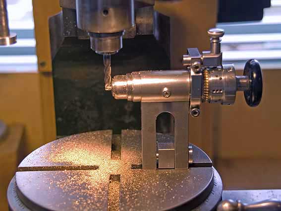
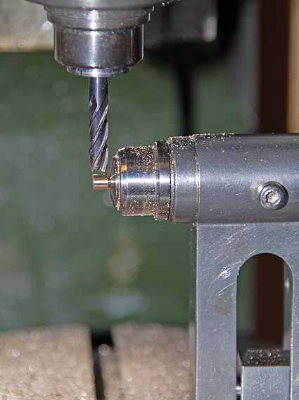

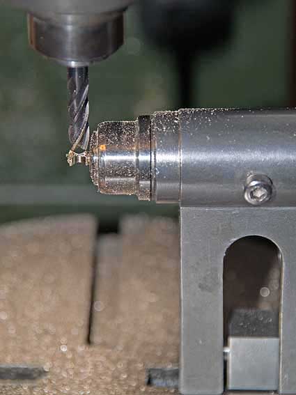
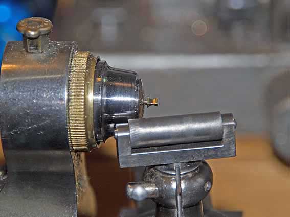
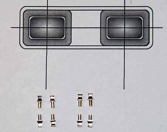
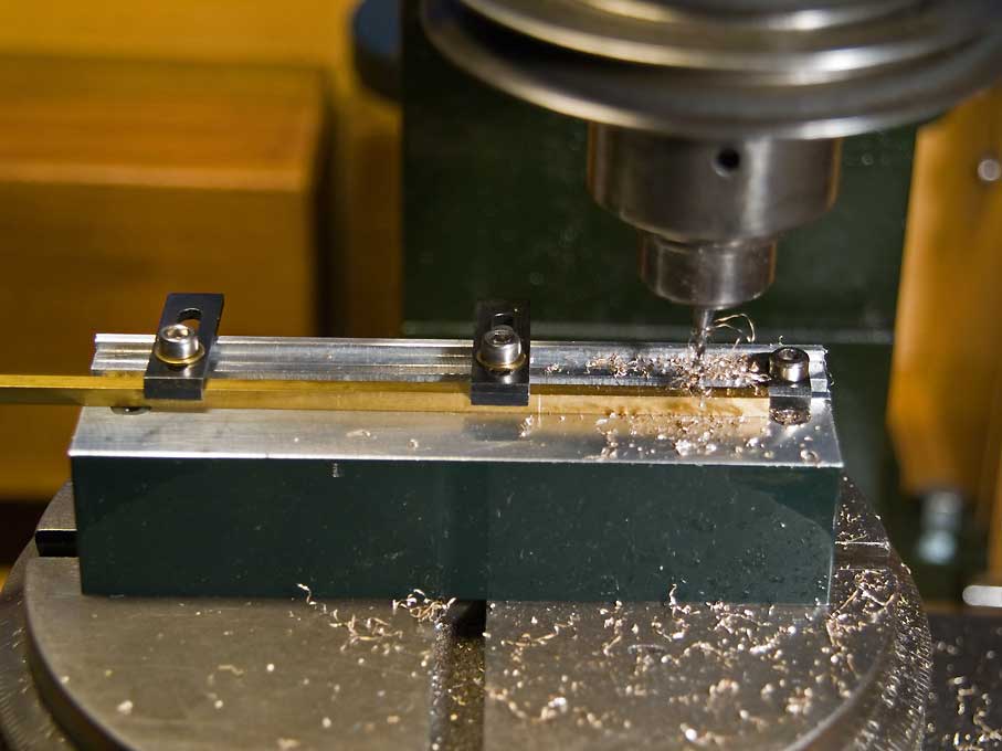
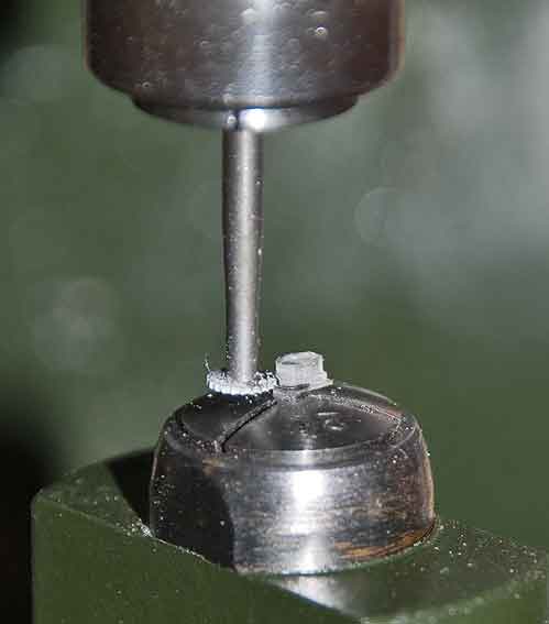
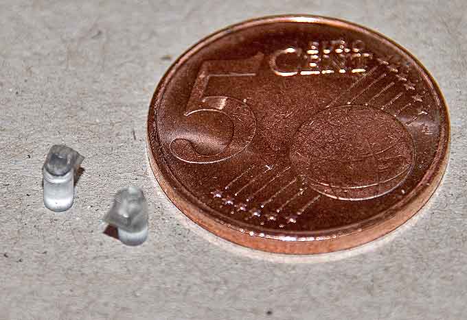
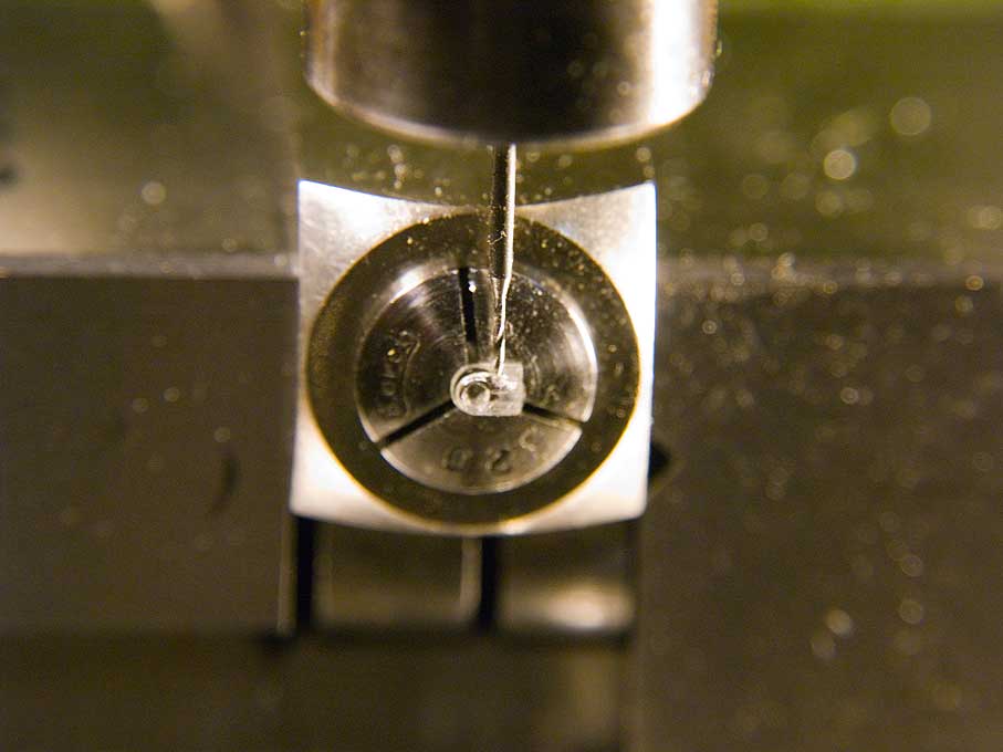
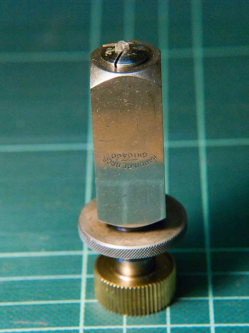
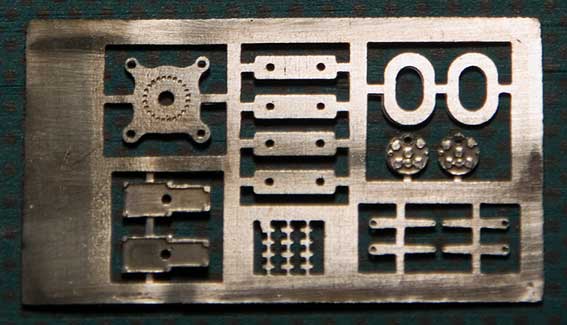
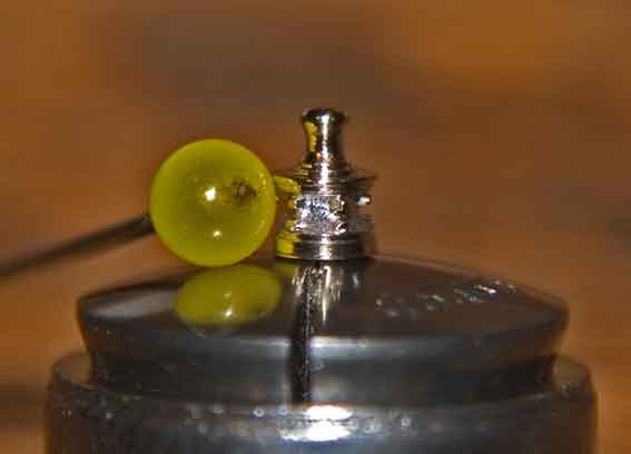
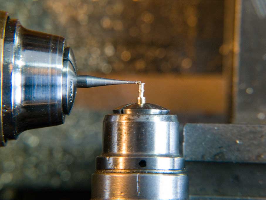
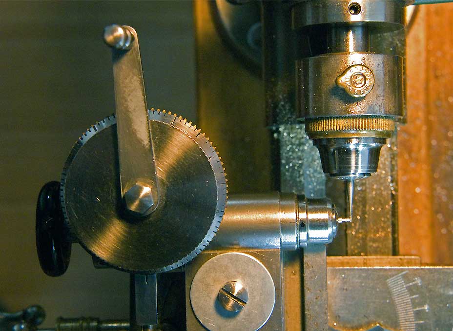
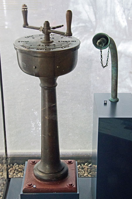
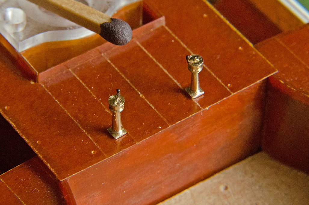
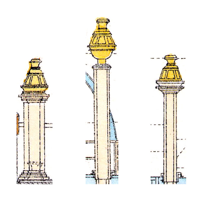
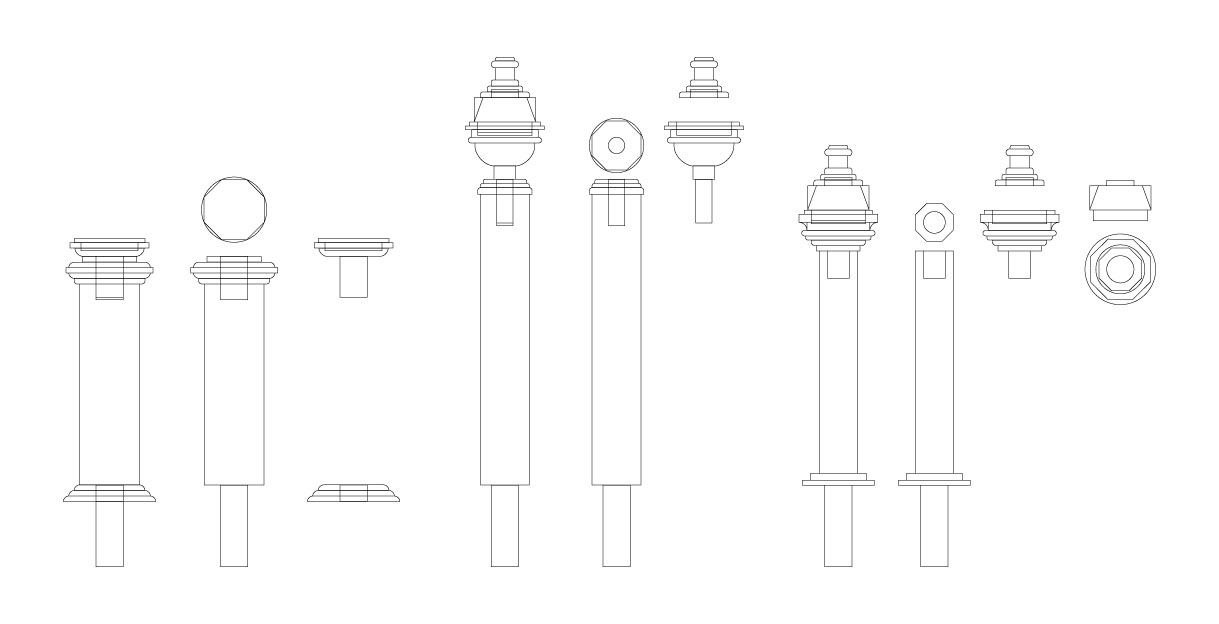
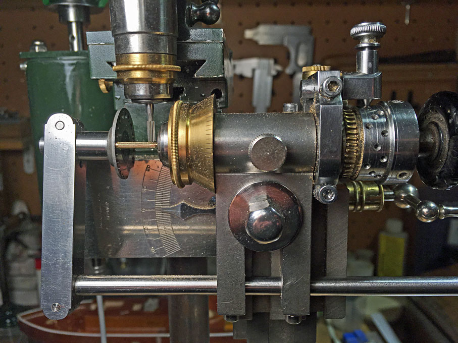
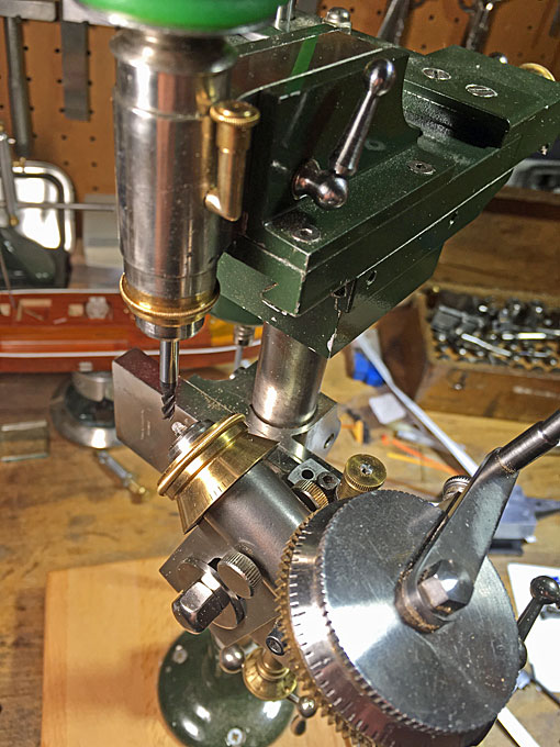
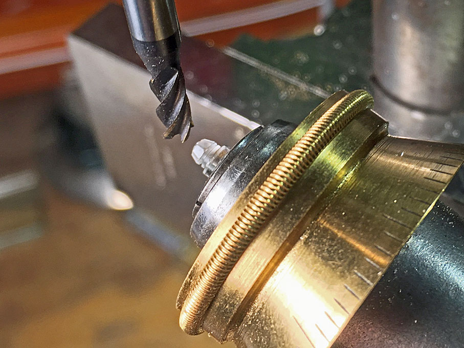
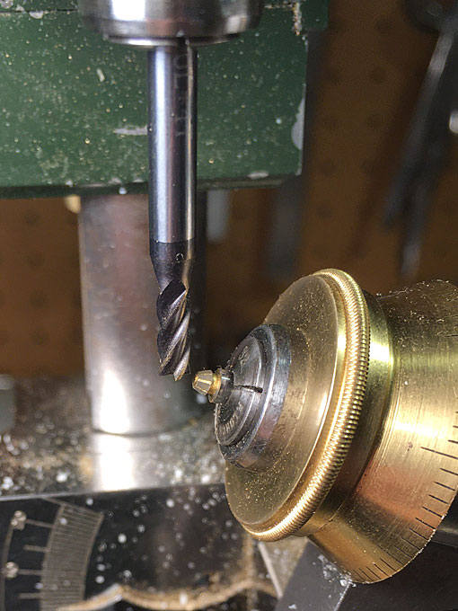
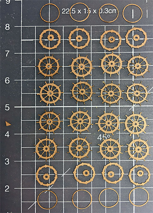
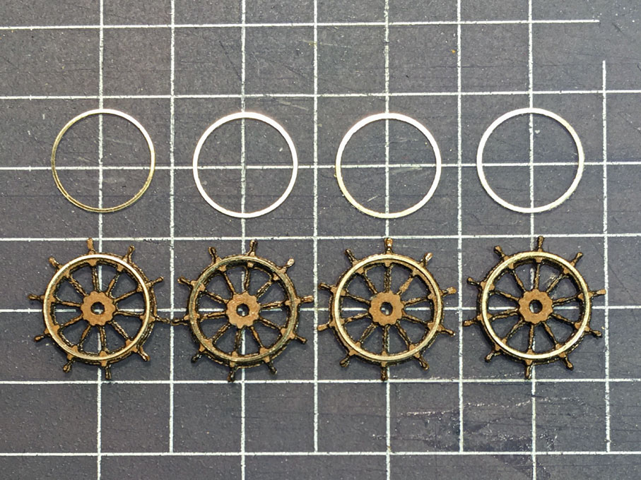
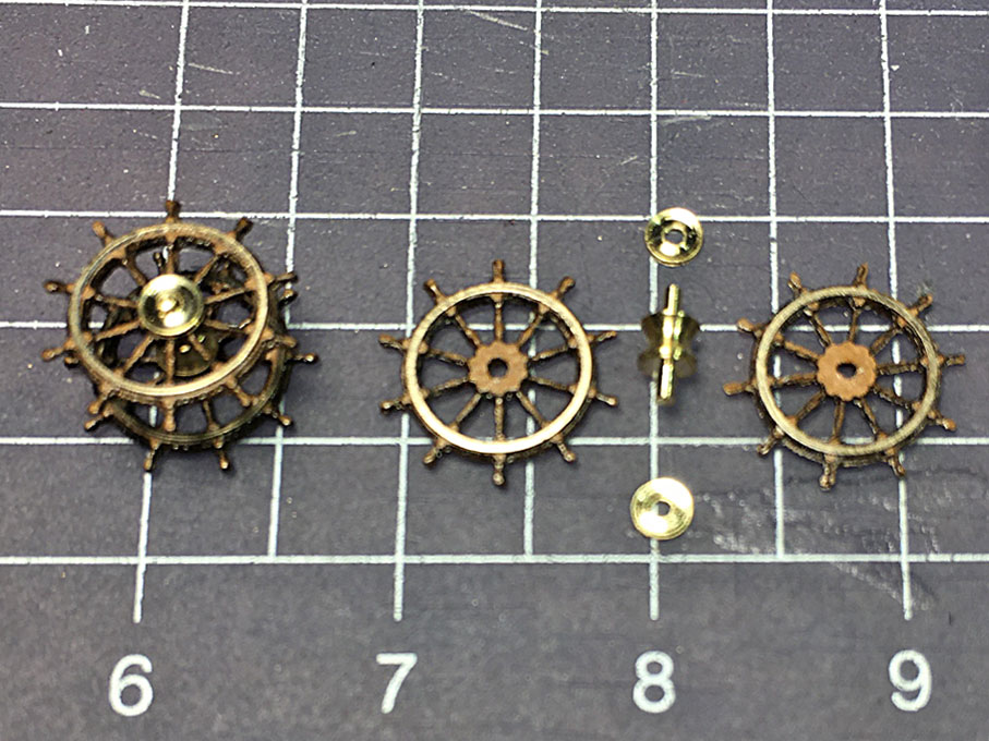
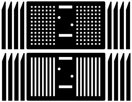
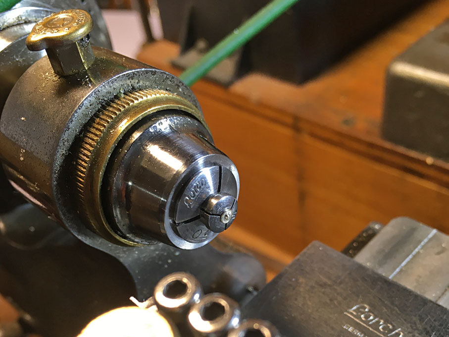
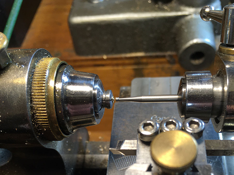
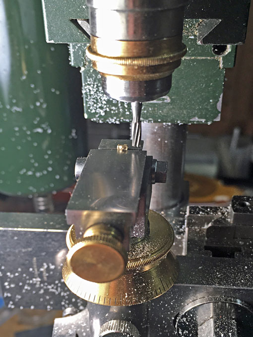
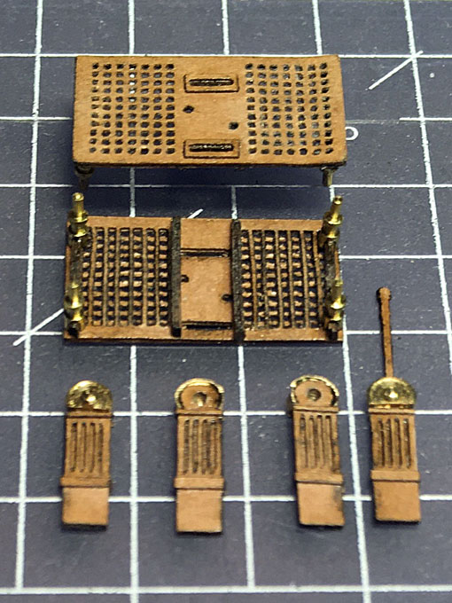
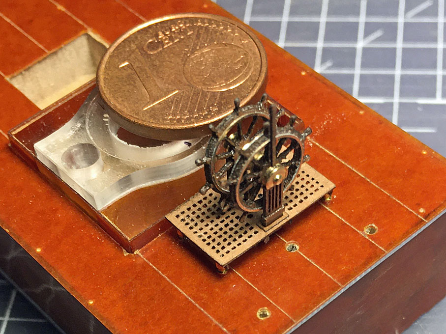
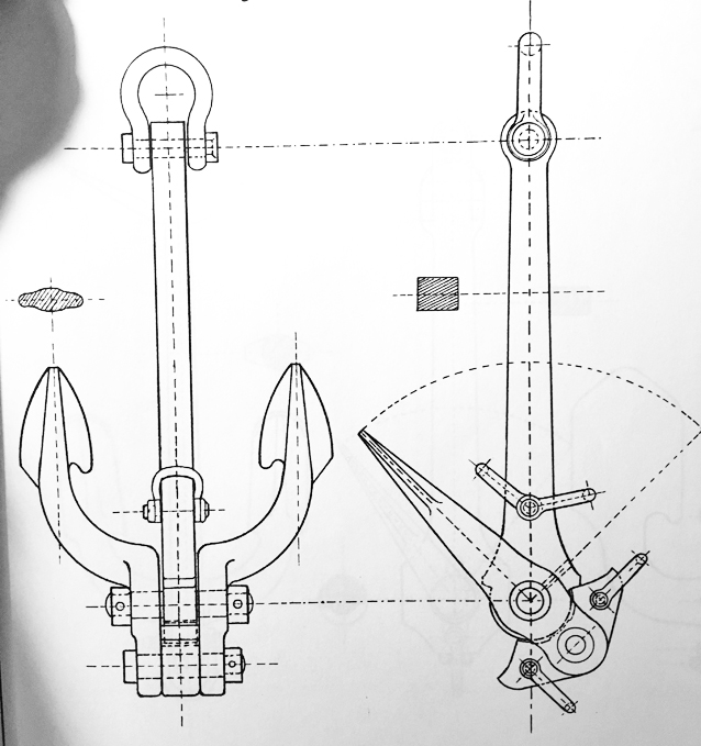
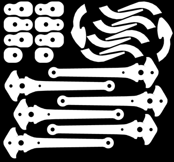
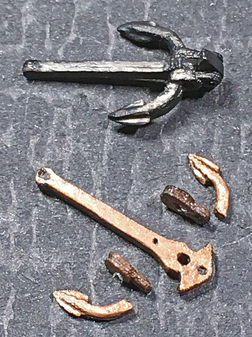
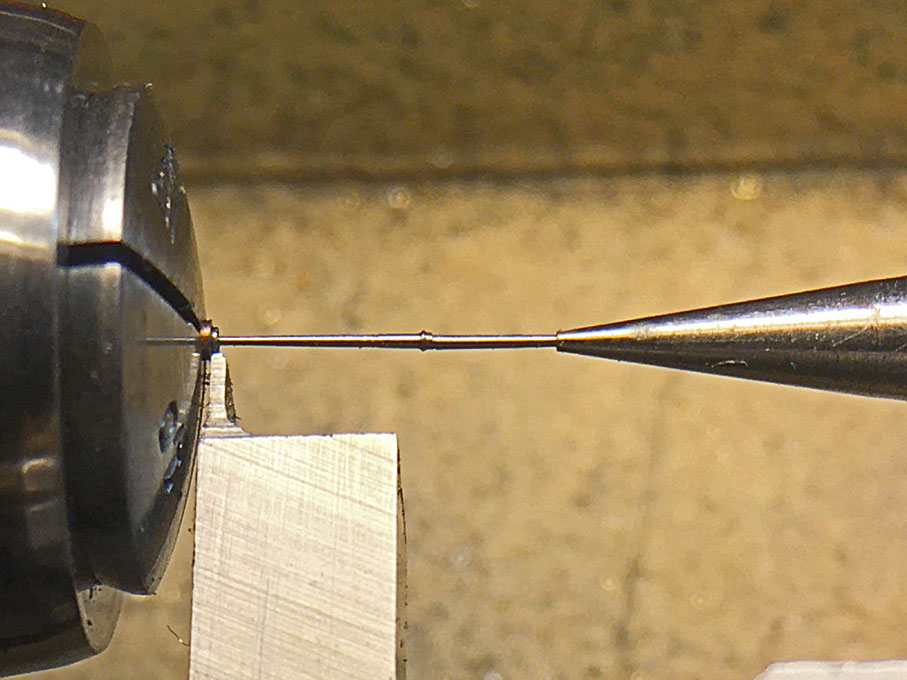
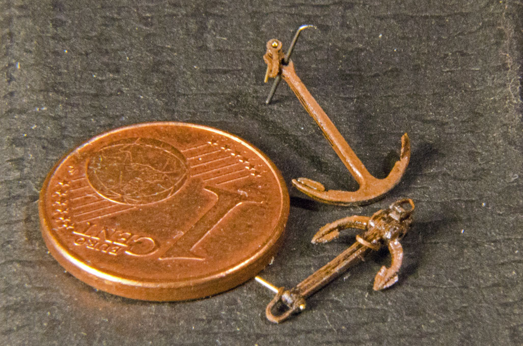
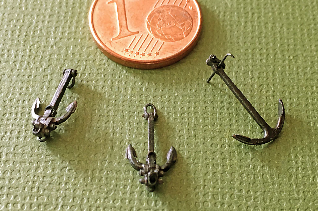
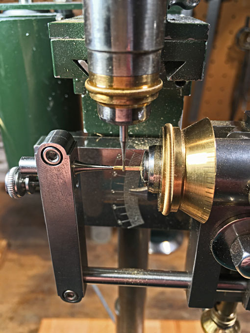
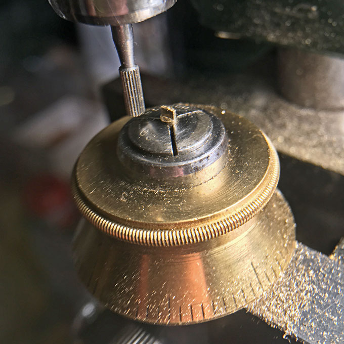
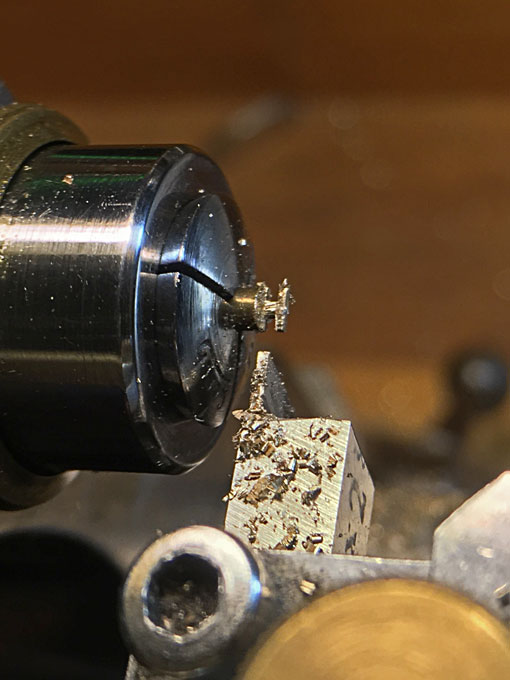
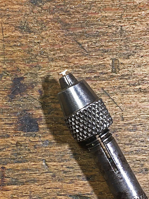
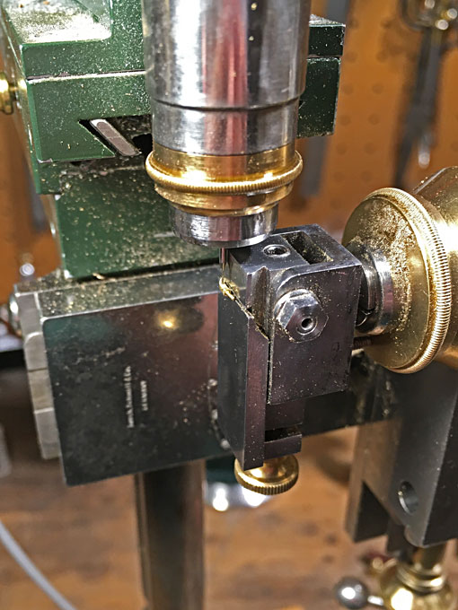
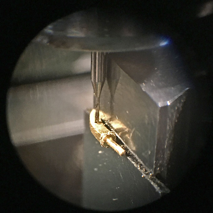
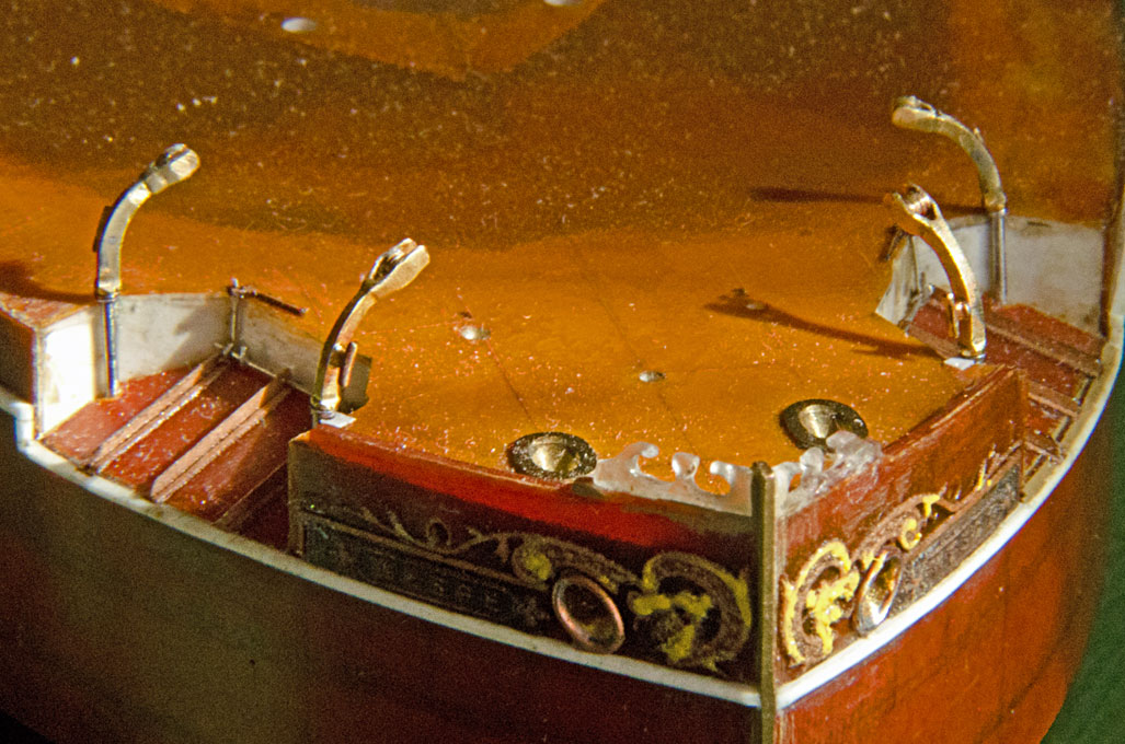
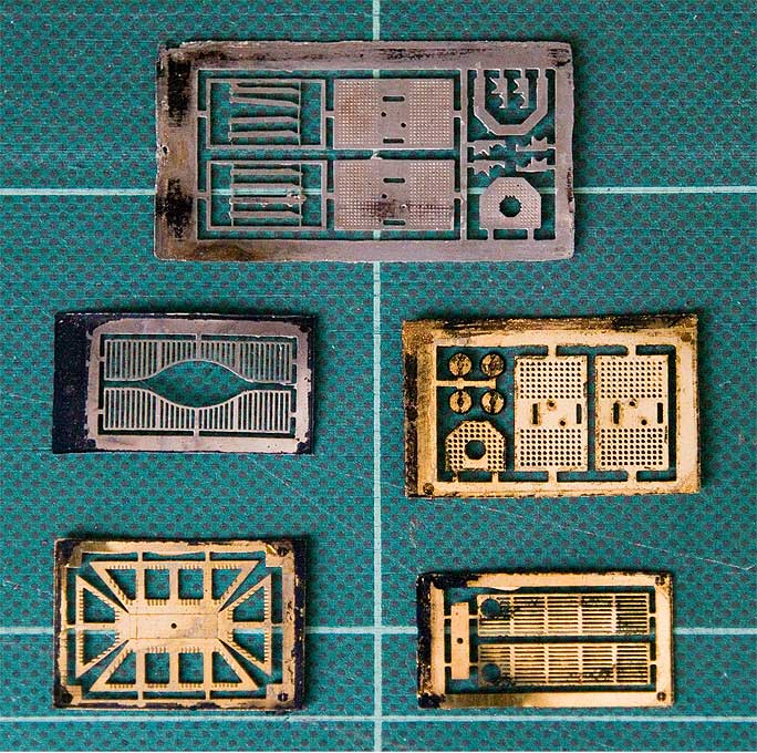
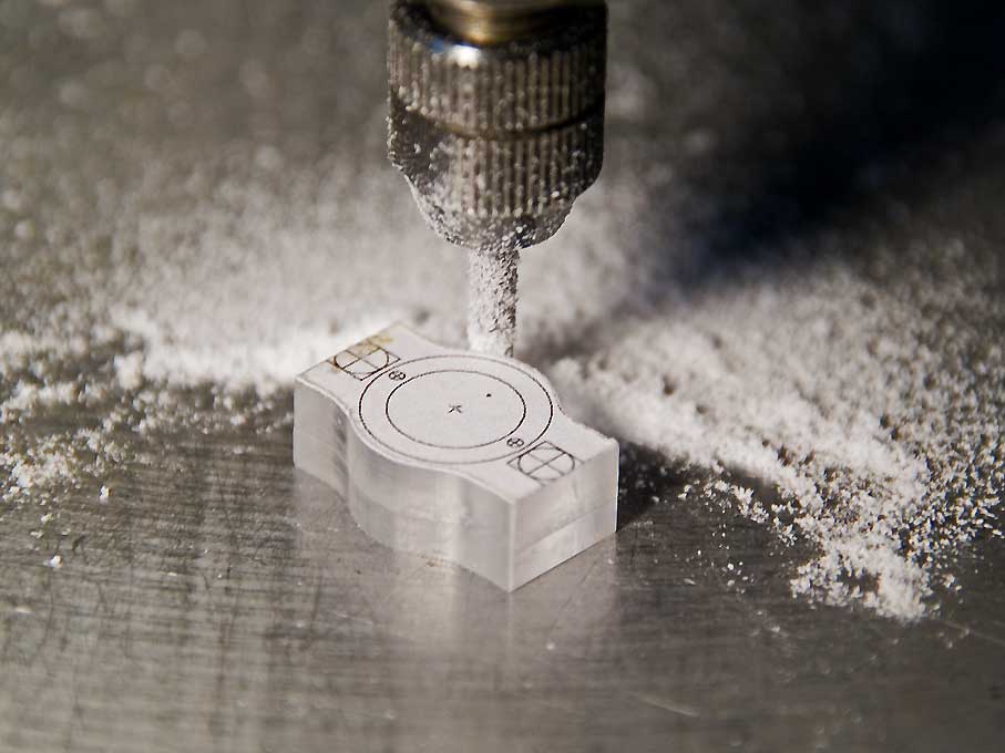
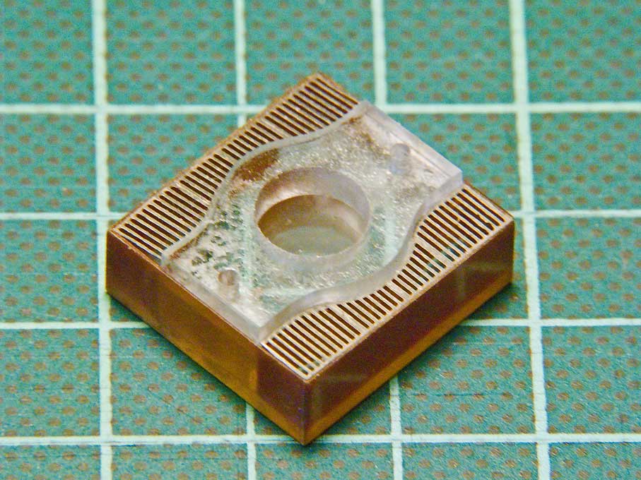
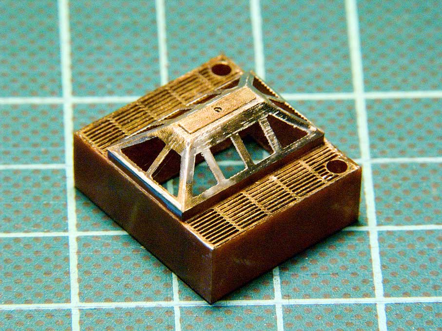
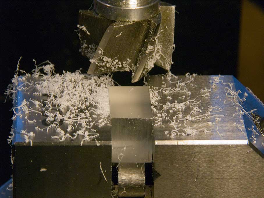
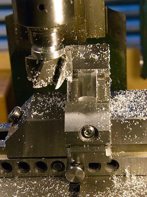
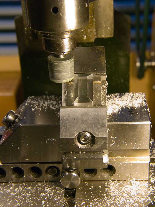
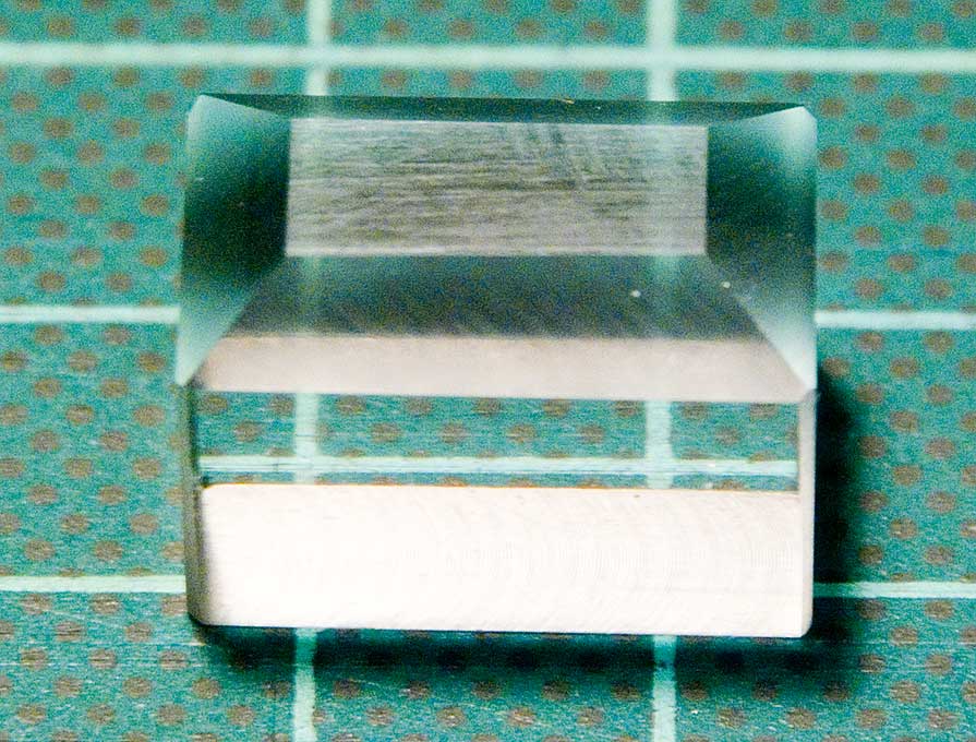
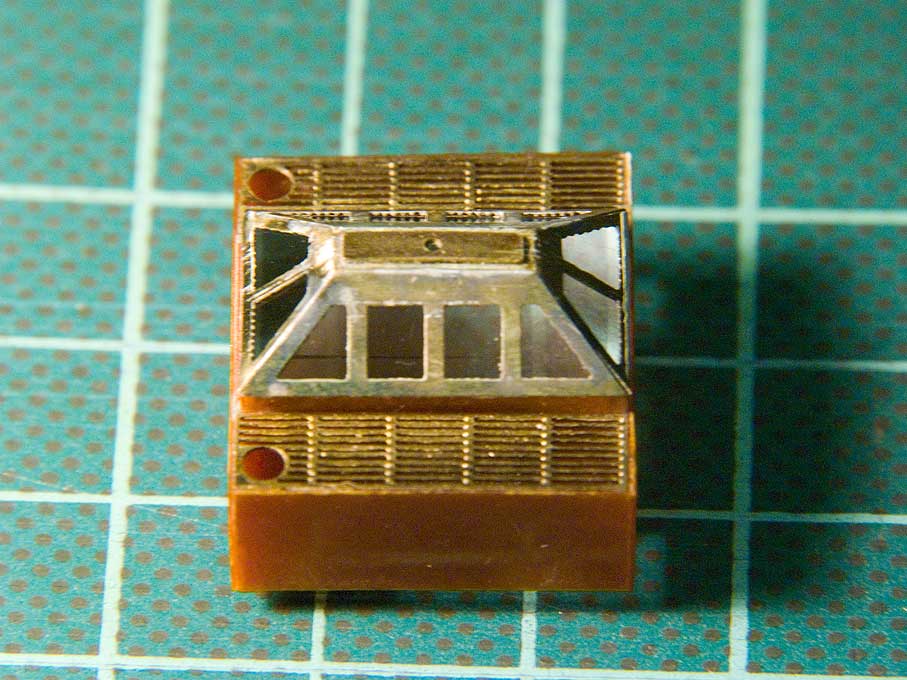
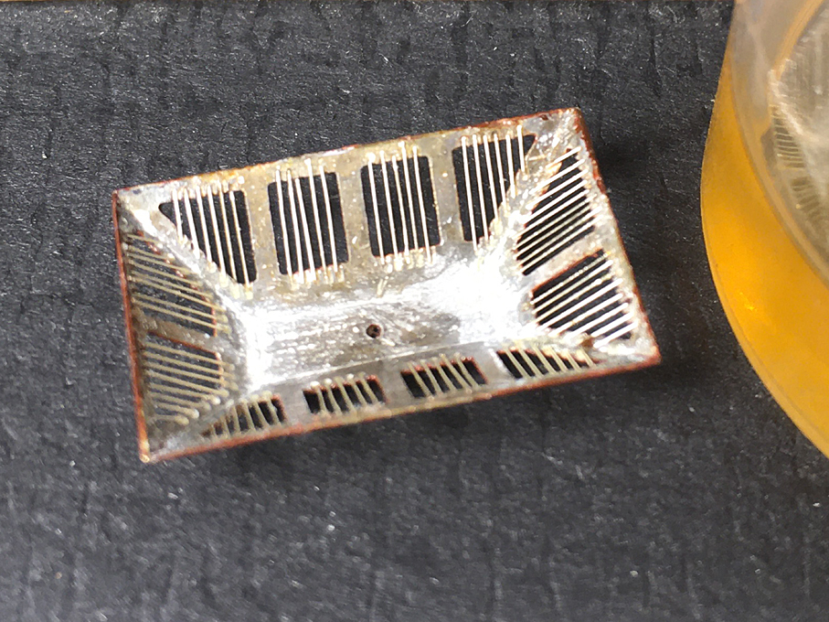
